LINEMAN SAFETY RULES FOR WORKING USING HOTLINE TOOLS
Hotline Tools Safety Rules
Follow these safety rules when working with hot-line tools:
• Do not perform hot-line work when rain or snow is threatening or when heavy dew, fog, or other excessive moisture is present. Exceptions to this rule are when conducting switching operations, fusing, or clearing damaged equipment that presents a hazard to the public or to troops.
• Remain alert. If rain or snow starts to fall or an electrical storm appears while a job is in progress, complete the work as quickly as possible to allow safe, temporary operation of the line until precipitation or lightning ceases. Judgment of safe weather conditions for hot-line work is the foreman's responsibility.
• Perform hot-line work during daylight if possible. In emergency situations, work under artificial light if all conductors and equipment being worked on are made clearly visible.
• Do not wear rubber gloves with hot-line tools because they make detection of brush discharges impossible.
• Avoid holding outer braces or other metal attachments.
• Avoid unnecessary conversation.
• Maintain close cooperation among everyone on the job.
• Treat wooden pole structures the same as steel towers.
• Be careful with distribution primaries. When they are located on the same pole with high-tension lines, cover them with rubber protective equipment before climbing through or working above them.
• Do not change your position on the pole without first looking around and informing others.
• Never use your hands to hold a live line clear of a lineman on a pole. Secure the line with live-line tools and lock it in a clamp.
• Stay below the live wire when moving it until it is thoroughly secured in a safe working position.
Take special precautions on poles having guy lines. Do not use a rope on conductors carrying more than 5,000 volts unless the rope is insulated from the conductor with an insulated tension link stick.
Showing posts with label Tools. Show all posts
Showing posts with label Tools. Show all posts
HAZARDS OF USING PNEUMATIC TOOLS BASIC INFORMATION AND TUTORIALS
WHAT ARE THE PNEUMATIC TOOLS HAZARD WHEN WORKING?
Hazard of Pneumatic Tools

Pneumatic tools are powered by compressed air and include chippers, drills, hammers, and sanders.
There are several dangers associated with the use of pneumatic tools. First and foremost is the danger of getting hit by one of the tool's attachments or by some kind of fastener the worker is using with the tool.
Pneumatic tools must be checked to see that the tools are fastened securely to the air hose to prevent them from becoming disconnected.
A short wire or positive locking device attaching the air hose to the tool must also be used and will serve as an added safeguard.
If an air hose is more than 12.7 millimeters in diameter, a safety excess flow valve must be installed at the source of the air supply to reduce pressure in case of hose failure.
In general, the same precautions should be taken with an air hose that are recommended for electric cords, because the hose is subject to the same kind of damage or accidental striking, and because it also presents tripping hazards.
When using pneumatic tools, a safety clip or retainer must be installed to prevent attachments such as chisels on a chipping hammer from being ejected during tool operation.
Pneumatic tools that shoot nails, rivets, staples, or similar fasteners and operate at pressures more than 6,890 kPa, must be equipped with a special device to keep fasteners from being ejected, unless the muzzle is pressed against the work surface.
Airless spray guns that atomize paints and fluids at pressures of 6,890 kPa or more must be equipped with automatic or visible manual safety devices that will prevent pulling the trigger until the safety device is manually released.
Eye protection is required, and head and face protection is recommended for employees working with pneumatic tools.
Screens must also be set up to protect nearby workers from being struck by flying fragments around chippers, riveting guns, staplers, or air drills.
Compressed air guns should never be pointed toward anyone. Workers should never "dead-end" them against themselves or anyone else. A chip guard must be used when compressed air is used for cleaning.
Use of heavy jackhammers can cause fatigue and strains. Heavy rubber grips reduce these effects by providing a secure handhold.
Workers operating a jackhammer must wear safety glasses and safety shoes that protect them against injury if the jackhammer slips or falls.
A face shield also should be used. Noise is another hazard associated with pneumatic tools. Working with noisy tools such as jackhammers requires proper, effective use of appropriate hearing protection.
Hazard of Pneumatic Tools
Pneumatic tools are powered by compressed air and include chippers, drills, hammers, and sanders.
There are several dangers associated with the use of pneumatic tools. First and foremost is the danger of getting hit by one of the tool's attachments or by some kind of fastener the worker is using with the tool.
Pneumatic tools must be checked to see that the tools are fastened securely to the air hose to prevent them from becoming disconnected.
A short wire or positive locking device attaching the air hose to the tool must also be used and will serve as an added safeguard.
If an air hose is more than 12.7 millimeters in diameter, a safety excess flow valve must be installed at the source of the air supply to reduce pressure in case of hose failure.
In general, the same precautions should be taken with an air hose that are recommended for electric cords, because the hose is subject to the same kind of damage or accidental striking, and because it also presents tripping hazards.
When using pneumatic tools, a safety clip or retainer must be installed to prevent attachments such as chisels on a chipping hammer from being ejected during tool operation.
Pneumatic tools that shoot nails, rivets, staples, or similar fasteners and operate at pressures more than 6,890 kPa, must be equipped with a special device to keep fasteners from being ejected, unless the muzzle is pressed against the work surface.
Airless spray guns that atomize paints and fluids at pressures of 6,890 kPa or more must be equipped with automatic or visible manual safety devices that will prevent pulling the trigger until the safety device is manually released.
Eye protection is required, and head and face protection is recommended for employees working with pneumatic tools.
Screens must also be set up to protect nearby workers from being struck by flying fragments around chippers, riveting guns, staplers, or air drills.
Compressed air guns should never be pointed toward anyone. Workers should never "dead-end" them against themselves or anyone else. A chip guard must be used when compressed air is used for cleaning.
Use of heavy jackhammers can cause fatigue and strains. Heavy rubber grips reduce these effects by providing a secure handhold.
Workers operating a jackhammer must wear safety glasses and safety shoes that protect them against injury if the jackhammer slips or falls.
A face shield also should be used. Noise is another hazard associated with pneumatic tools. Working with noisy tools such as jackhammers requires proper, effective use of appropriate hearing protection.
HOTLINE TOOLS SAFETY RULES BASIC INFORMATION AND TUTORIALS
What are the safety rules in using hotline tools?

Follow these safety rules when working with hot-line tools:
• Do not perform hot-line work when rain or snow is threatening or when heavy dew, fog, or other excessive moisture is present. Exceptions to this rule are when conducting switching operations, fusing, or clearing damaged equipment that presents a hazard to the public or to troops.
• Remain alert. If rain or snow starts to fall or an electrical storm appears while a job is in progress, complete the work as quickly as possible to allow safe, temporary operation of the line until precipitation or lightning ceases. Judgment of safe weather conditions for hot-line work is the foreman's responsibility.
• Perform hot-line work during daylight if possible. In emergency situations, work under artificial light if all conductors and equipment being worked on are made clearly visible.
• Do not wear rubber gloves with hot-line tools because they make detection of brush discharges impossible.
• Avoid holding outer braces or other metal attachments.
• Avoid unnecessary conversation.
• Maintain close cooperation among everyone on the job.
• Treat wooden pole structures the same as steel towers.
• Be careful with distribution primaries. When they are located on the same pole with high-tension lines, cover them with rubber protective equipment before climbing through or working above them.
• Do not change your position on the pole without first looking around and informing others.
• Never use your hands to hold a live line clear of a lineman on a pole. Secure the line with live-line tools and
lock it in a clamp.
• Stay below the live wire when moving it until it is thoroughly secured in a safe working position.
• Take special precautions on poles having guy lines.
• Do not use a rope on conductors carrying more than 5,000 volts unless the rope is insulated from the conductor with an insulated tension link stick.
SAFETY USE OF GRINDING AND POLISHING MACHINES BASIC INFORMATION
How to use safely grinding and polishing machines?

Provide every grinding or polishing machine which generates dust with an efficient exhaust system or dust abatement system. The exhaust system should consist of a hood ducted to an exhaust fan in such a manner as to carry away the dust to a device whereby the dust is separated from the air and is prevented from entering the workroom.
All personnel engaged in grinding or polishing operations must wear suitable eye protection.
Properly mount grinding wheels, and where necessary, fit with a bush of suitable material between the wheel and the spindle. A guard of sufficient mechanical strength should enclose the grinding wheel.
It is necessary to prevent vibration, which can be caused by incorrect wheel balance, lack of rigidity in the machine, loose bearings or incorrect use of the work rest. Additionally, incorrect fitting of the belt fasteners for a belt-driven wheel may cause the vibration.
Provide an eye screen for hand-held work when using pedestal or bench-type grinding machines. The area of the screen should be large enough to discourage the operator from looking around it.
The screen should always be in place and maintained at an adequate transparency.
Every grinding wheel should be positioned so that when in use the plane of rotation is not in line with any door, passageway, entrance or a place where someone regularly works.
Finishing machines should be guarded with only the working face of the belt exposed and the belt should be mounted such that it rotates away from the operator wherever practicable. Before use the condition of abrasive belt should be examined and replaced if worn and the correctness of the tracking of the belt should be checked by rotating the belt by hand.
If necessary the belt should be adjusted and finally checked with a trial run. Where possible suitable jigs
or fixtures should be used to hold or locate the work piece.
The work piece should never be held in a cloth or any form of pliers and gloves must not be worn when using a finishing machine.
SAFE USE OF HYDRAULIC POWER TOOLS BASIC INFORMATION
How to safely use hydraulic power tools?
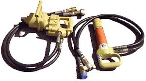
The fluid used in hydraulic power tools must be an approved fire resistant fluid and must retain its operating characteristics at the most extreme temperatures to which it will be exposed. The exception to fire-resistant fluid involves all hydraulic fluids used for the insulated sections of derrick trucks, aerial lifts, and hydraulic tools that are used on or around energized lines.
Do not exceeded the manufacturer's recommended safe operating pressure for hoses, valves, pipes, filters, and other fittings.
All jacks - including lever and ratchet jacks, screw jacks, and hydraulic jacks - must have a stop indicator, and the stop limit must not be exceeded. Also, the manufacturer's load limit must be permanently marked in a prominent place on the jack, and the load limit must not be exceeded.
Never use a jack to support a lifted load. Once the load has been lifted, it must immediately be blocked up. Put a block under the base of the jack when the foundation is not firm, and place a block between the jack cap and load if the cap might slip.
To set up a jack, make certain of the following:
• The base of the jack rests on a firm, level surface;
• The jack is correctly centered;
• The jack head bears against a level surface; and
• The lift force is applied evenly
All jacks must be lubricated regularly Additionally, each jack must be inspected according to the following schedule:
• for jacks used continuously or intermittently at one site - inspected at least once every 6 months;
• for jacks sent out of the shop for special work- inspected when sent out and inspected when returned; and
• for jacks subjected to abnormal loads or shock - inspected before use and immediately thereafter.
DANGER OF POWER TOOLS - WHAT ARE THE DANGER OF POWER TOOLS BASICS
Be extra careful in handling power tools.

Power tools are determined by their power source: electric, pneumatic, liquid fuel, hydraulic, and powder-actuated. Power tools should be equipped with guards and safety switches.
Personal protective equipment such as safety goggles and gloves should be worn to protect against hazards that may be encountered while using power tools.
To prevent hazards associated with the use of power tools, workers should observe the following general precautions:
1 Never carry a tool by the cord or hose.
2 Never yank the cord or the hose to disconnect it from the receptacle.
3 Keep cords and hoses away from heat, oil, and sharp edges.
4 Disconnect tools when not using them, before servicing and cleaning them, and when changing accessories
such as blades, bits, and cutters.
5 Keep all people not involved with the work at a safe distance from the work area.
6 Secure work with clamps or a vise, freeing both hands to operate the tool.
7 Avoid accidental starting. Do not hold fingers on the switch button while carrying a plugged-in tool.
8 Maintain tools with care; keep them sharp and clean for best performance.
9 Follow instructions in the user's manual for lubricating and changing accessories.
10 Be sure to keep good footing and maintain good balance when operating power tools.
11 Wear proper apparel for the task. Loose clothing, ties, or jewelry can become caught in moving parts.
Remove all damaged portable electric tools from use and tag them:
"Do Not Use.
THE DANGERS OF ASBESTOS - BASIC INFORMATION AND TUTORIALS
What are the dangers of inhaling asbestos in construction?
Inhaling asbestos dust has been shown to cause the following diseases:
• asbestosis
• lung cancer
• mesothelioma (cancer of the lining of the chest and/or abdomen).
Asbestosis is a disease of the lungs caused by scar tissue forming around ve ry small asbestos fibres deposited deep in the lungs. As the amount of scar tissue increases, the ability of the lungs to expand and contract decreases, causing shortness of breath and a heavier wo rkload on the heart.
Ultimately, asbestosis can be fatal.
Lung cancer appears quite frequently in people exposed to asbestos dust.While science and medicine have not yet been able to explain precisely why or how asbestos causes lung cancer to develop, it is clear that exposure to asbestos dust can increase the risk of contracting this disease.
Studies of asbestos wo rkers have shown that the risk is roughly five times greater than for people who are not exposed to asbestos.
Cigarette smoking, another cause of lung cancer, multiplies this risk . Research has shown that the risk of developing cancer is fifty times higher for asbestos workers who smoke than for workers who neither smoke nor work with asbestos.
Mesothelioma is a relatively rare cancer of the lining of the chest and/or abdomen.While this disease is seldom observed in the general population, it appears frequently in groups exposed to asbestos.
Other illnesses—There is also some evidence of an increased risk of cancer of the stomach, rectum, and larynx. However, the link between asbestos exposure and the development of these illnesses is not as clear as with lung cancer or mesothelioma.
The diseases described above do not respond well to current medical treatment and, as a result, are often fatal.
HOW TO MAKE ACCURATE SINGLE LINE DIAGRAM FOR POWER SYSTEM TUTORIALS
What are the elements of an accurate single line diagram?
A reliable single-line diagram of an industrial or commercial electrical power distribution system is an invaluable tool. It is also called a one-line diagram. The single-line diagram indicates, by single lines and standard symbols, the course and component parts of an electric circuit or system of circuits. The symbols that are commonly used in one-line diagrams are defined in IEEE Std 315-1975.
The single-line diagram is a road map of the distribution system that traces the ßow of power into and through the system. The single-line drawing identifiers the points at which power is, or can be, supplied into the system and at which power should be disconnected in order to clear, or isolate, any portion of the system.
Characteristics of an accurate diagram
The following characteristics should help to ensure accuracy as well as ease of interpretation:
a) Keep it simple
A fundamental single-line diagram should be made up of short, straight lines and components, similar to the manner in which a block diagram is drawn. It should be relatively easy to get the overall picture of the whole electrical system.
All, or as much as possible, of the system should be kept to one sheet. If the system is very large, and more than one sheet is necessary, then the break should be made at voltage levels or at distribution centers.
b) Maintain relative geographic relations
In many cases, it is possible to superimpose a form of the one-line diagram onto the facility plot plan. This is very helpful toward a quick understanding of the location of the system's major components for operating purposes.
It may, however, be more difficult to comprehend the overall system operation from this drawing. Such a drawing could be used for relatively simple systems. For more complex systems, however, it should be used in addition to the fundamental single-line diagram.
c) Maintain the approximate relative positions of components when producing the single-line diagram
The drawing should be as simple as possible and should be laid out in the same relationship as an operator would view the equipment. The diagram does not need to show geographical relationships at the expense of simplicity.
NOTE: A site plan with equipment locations may be required to accompany the single-line diagram.
d) Avoid duplication
Each symbol, figure, and letter has a definite meaning. The reader should be able to interpret each without any confusion. In this regard, equipment names should be selected before publishing the document; then, these names should be used consistently.
e) Show all known factors
All details shown on the diagram are important. Some of those important details are as follows:
Ñ ManufacturersÕ type designations and ratings of apparatus;
Ñ Ratios of current and potential transformers and taps to be used on multi-ratio transformers;
Ñ Connections of power transformer windings;
Ñ Circuit breaker ratings in volts, amperes, and short-circuit interrupting rating;
Ñ Switch and fuse ratings in volts, amperes, and short-circuit interrupting rating;
Ñ Function of relays. Device functions used should be from IEEE Std C37.2-1991;
Ñ Ratings of motors, generators, and power transformers;
Ñ Number, size, and type of conductors;
Ñ Voltage, phases, frequency, and phase rotation of all incoming circuits. The type
of supply system (wye or delta, grounded or ungrounded) and the available
short-circuit currents should be indicated.
f) Future plans
When future plans are known, they should be shown on the diagram or explained by notes.
g) Other considerations
Refer to IEEE Std 141-1993 for further discussion of singleline diagrams.
BEST LOCATIONS FOR PANEL BOARDS AND SWITCH BOARDS OF ELECTRONIC EQUIPMENT BASIC TUTORIALS
Where should panel boards be located?
Switchboards and panelboards that support electronic load equipment and related loads should be properly designed and installed. Recommended practice is to use panelboards specifically listed for nonlinear loads if they serve electronic load equipment.
As a minimum, panelboards should be rated for power or lighting applications, and should not be a lighterduty type. Special attention should be given to the location and installation methods used when installing panelboards.
In addition, protective devices shall adequately protect system components, neutral buses should be sized to accommodate increased neutral currents due to harmonic currents from nonlinear electronic load equipment, and equipment ground buses should be sized to accommodate increased numbers of equipment grounding conductors due to the recommended practices of using insulated equipment grounding conductors and dedicated circuits for electronic load equipment.
Surge protective devices may also be installed external to, or internal to, the switchboards or panelboards.
Location
Panelboards that serve electronic load equipment should be placed as near to the electronic load equipment as practicable, and should be bonded to the same ground reference as the electronic load equipment.
Other panelboards located in the same area as the electronic load equipment that serve other loads such as lighting, heating, ventilation, air conditioning, and process cooling equipment should also be bonded to the same ground reference as the electronic load equipment.
Panelboards should be directly mounted to any building steel member in the immediate area of the installation. Isolation of a panelboard from the metallic building structure by an electrically insulating material, as an attempt to prevent flow of high frequency current through the panelboard, is not recommended practice.
The panelboard and metallic building structure, separated by a dielectric material, become capacitively coupled. The capacitive coupling presents a low impedance at high frequency defeating the original purpose.
NFPA 780-1997 requires effective grounding and bonding between objects such as structural building steel and a panelboard located within side-flash distance (approximately 1.8 m (6 ft), horizontally) of each other. Insulation materials, commonly used in an attempt to separate a panelboard from building steel, are rarely capable of withstanding lightningi nduced arcing conditions.
TYPES OF AC GENERATOR ROTORS BASIC INFORMATION AND TUTORIALS
Synchronous AC generators are fitted with one of two different rotor designs depending on their intended rotational speeds.
Round rotors are solid steel cylinders with the field winding inserted in slots milled into the surface or the rotor. They usually have two or four poles. Round rotors can withstand the stresses of high-speed rotation.

Salient-pole rotors have multiple pole pieces (typically six) mounted to the rotor structure, and the field winding is wound around the pole pieces. Because of their more complex construction and larger diameter-to-length ratios, salient-pole rotors cannot withstand the stresses of high-speed rotation.

Electric utility steam-turbine–driven generators designed for 50- or 60-Hz AC output voltage have round rotors with two poles because they can withstand the stresses of speeds of 3000 and 3600 rpm.
Hydroelectric, diesel, and natural-gas engines have far lower shaft speeds than steam turbines, so the generators they drive usually have six or more pole rotors, requirements usually met with more complex salient-pole rotors.
Three-phase AC generators have a winding that is made up of three separate stator windings, each displaced from the other two by 120 electrical degrees. The three windings can either be wye- or delta-connected. The wye connection is more common because it is better suited for direct high-voltage generation.
Round rotors are solid steel cylinders with the field winding inserted in slots milled into the surface or the rotor. They usually have two or four poles. Round rotors can withstand the stresses of high-speed rotation.
Salient-pole rotors have multiple pole pieces (typically six) mounted to the rotor structure, and the field winding is wound around the pole pieces. Because of their more complex construction and larger diameter-to-length ratios, salient-pole rotors cannot withstand the stresses of high-speed rotation.
Electric utility steam-turbine–driven generators designed for 50- or 60-Hz AC output voltage have round rotors with two poles because they can withstand the stresses of speeds of 3000 and 3600 rpm.
Hydroelectric, diesel, and natural-gas engines have far lower shaft speeds than steam turbines, so the generators they drive usually have six or more pole rotors, requirements usually met with more complex salient-pole rotors.
Three-phase AC generators have a winding that is made up of three separate stator windings, each displaced from the other two by 120 electrical degrees. The three windings can either be wye- or delta-connected. The wye connection is more common because it is better suited for direct high-voltage generation.
ELECTRICAL OVERLOADING - THE HAZARDS OF OVERLOADING BASIC INFORMATION
Overloads in an electrical system are hazardous because they can produce heat or arcing. Wires and other components in an electrical system or circuit have a maximum amount of current they can carry safely.
If too many devices are plugged into a circuit, the electrical current will heat the wires to a very high temperature. If any one tool uses too much current, the wires will heat up.
The temperature of the wires can be high enough to cause a fire. If their insulation melts, arcing may occur. Arcing can cause a fire in the area where the overload exists, even inside a wall.
In order to prevent too much current in a circuit, a circuit breaker or fuse is placed in the circuit. If there is too much current in the circuit, the breaker “trips” and opens like a switch.
If an overloaded circuit is equipped with a fuse, an internal part of the fuse melts, opening the circuit. Both breakers and fuses do the same thing: open the circuit to shut off the electrical current.
If the breakers or fuses are too big for the wires they are supposed to protect, an overload in the circuit will not be detected and the current will not be shut off. Overloading leads to overheating of circuit components (including wires) and may cause a fire.
You need to recognize that a circuit with improper overcurrent protection devices—or one with no overcurrent protection devices at all— is a hazard.
Overcurrent protection devices are built into the wiring of some electric motors, tools, and electronic devices. For example, if a tool draws too much current or if it overheats, the current will be shut off from within the device itself.
Damaged tools can overheat and cause a fire. You need to recognize that a damaged tool is a hazard.
WORKS REQUIRING PERMITS BASIC INFORMATION AND TUTORIALS
What are the activities/ works that requires work permit?
The main types of permit and the work to be covered by each are identified below. Appendix 6.4 illustrates the essential elements of a permit form with supporting notes on its operation.
General permit
The general permit should be used for work such as:
S alterations to or overhaul of plant or machinery where mechanical, toxic or electrical hazards may arise
S work on or near overhead crane tracks
S work on pipelines with hazardous contents
S work with asbestos-based materials
S work involving ionising radiation
S work at height where there are exceptionally high risks
S excavations to avoid underground services.
Confined space permit
Confined spaces include chambers, tanks (sealed and open-top), vessels, furnaces, ducts, sewers, manholes, pits, flues, excavations, boilers, reactors and ovens.
Many fatal accidents have occurred where inadequate precautions were taken before and during work involving entry into confined spaces. The two main hazards are the potential presence of toxic or other dangerous substances and the absence of adequate oxygen.
In addition, there may be mechanical hazards (entanglement on agitators) and raised temperatures. The work to be carried out may itself be especially hazardous when done in a confined space, for example, cleaning using solvents, cutting/welding work.
Should the person working in a confined space get into difficulties for whatever reason, getting help in and
getting the individual out may prove difficult and dangerous.
Stringent preparation, isolation, air testing and other precautions are therefore essential and experience shows that the use of a confined space entry permit is essential to confirm that all the appropriate precautions
have been taken.
Work on high voltage apparatus (including testing)
Work on high voltage apparatus (over about 600 volts) is potentially high risk. Hazards include:
S possibly fatal electric shock/burns to the people doing the work
S electrical fires/explosions
S consequential danger from disruption of power supply to safety-critical plant and equipment.
In view of the risk, this work must only be done by suitably trained and competent people acting under the terms of a high voltage permit.
Hot work
Hot work is potentially hazardous as a:
S source of ignition in any plant in which highly flammable materials are handled
S cause of fires in all locations, regardless of whether highly flammable materials are present.
Hot work includes cutting, welding, brazing, soldering and any process involving the application of a naked
flame. Drilling and grinding should also be included where a flammable atmosphere is potentially present.
In high risk areas hot work may also involve any equipment or procedure that produces a spark of sufficient energy to ignite highly flammable substances.
Hot work should therefore be done under the terms of a hot work permit, the only exception being where hot work is done in a designated area suitable for the purpose.
POWER CIRCUIT BREAKER TYPES FOR SAFETY INFORMATION BASICS
The five general types of high-voltage circuit breakers are as follows.
1 Oil circuit breakers use standard transformer oil, an effective medium for quenching the arc and providing an open break after current has dropped to zero. There are two general types of oil circuit breakers: dead-tank for the higher voltage ranges and live-tank for lower voltages.
Oil circuit breakers have been improved by adding such features as oil-tight joints, vents, and separate chambers to prevent the escape of oil.
Also, improved operating mechanisms prevent gas pressure from reclosing the contacts, making them reliable for system voltages up to 362 kV. However, above 230 kV, oil-less breakers are more economical.
2 Air-blast circuit breakers were developed as alternatives to oil circuit breakers as voltages increased. They depend on the good insulating and arc-quenching properties of dry and clean compressed air injected into the contact region.
3 Magnetic-air circuit breakers use a combination of strong magnetic field with a special arc chute to lengthen the arc until the system voltage is unable to maintain the arc any longer. They are used principally in power distribution systems.
4 Gas circuit breakers take advantage of the excellent arc-quenching and insulating properties of sulfur hexafluoride (SF6) gas. These outdoor breakers can interrupt system voltages up to 800 kV.
These circuit breakers are typically included in gasinsulated substations (GISs) that offer space-saving and environmental advantages over conventional outdoor substations. Gas (SF6) circuit breakers are made with ratings up to 800 kV and continuous cur rent up to 4000 A.
They are alternatives to oil and vacuum breakers for metal-clad and metal-enclosed switchgear up to 38 kV.
5 Vacuum circuit breakers, more accurately termed vacuum-bottle interrupters, are generally used for voltages up to 38 kV and continuous current ratings to 3000 A.
They are used for higher system voltage, current, and interrupting ratings, and are typically specified for metal-clad and metal-enclosed switchgear in distribution systems.
ELECTRICAL PROTECTIVE HIGH TENSION GLOVES BASIC INFORMATION AND TUTORIALS
What are high tension gloves?
High voltage gloves are a form of PPE that is required for employees who work in close proximity to live electrical current. OSHAs Electrical Protective Equipment Standard (29 CFR 1910.137) provides the design guidelines and in-service care and use requirements for electrical insulating gloves and sleeves as well as insulating blankets, matting, covers, and line hoses.

Electrical protective gloves are categorized by the level of voltage protection they provide. Voltage protection is broken down into the following classes:
n Class 0—Maximum use voltage of 1000 V AC/proof tested to 5000 V AC.
n Class 1—Maximum use voltage of 7500 V AC/proof tested to 10,000 V AC.
n Class 2—Maximum use voltage of 17,000 V AC/proof tested to 20,000 V AC.
n Class 3—Maximum use voltage of 26,500 V AC/proof tested to 30,000 V AC.
n Class 4—Maximum use voltage of 36,000 V AC/proof tested to 40,000 V AC.
Once the gloves are issued, OSHA requires that they be maintained in a safe, reliable condition. This means that high voltage gloves must be inspected for any damage before each day’s use, and immediately following any incident that may have caused them to be damaged.
This test method is described in the ASTM section F 496, Specification for In-Service Care of Insulating Gloves and Sleeves. Basically, the glove is filled with air, manually or by an inflator, and then checked for leakage.
The easiest way to detect leakage is by listening for air escaping or holding the glove against your cheek to feel air releasing.
OSHA recognizes that gloves meeting ASTM D 120-87, Specification for Rubber Insulating Gloves, and ASTM F 496, Specification for In- Service Care of Insulating Gloves and Sleeves, meet its requirements.
In addition to daily testing, OSHA requires periodic electrical tests for electrical protective equipment and ASTM F 496 specifies that gloves must be electrically retested every 6 months. Many power utility companies will test gloves and hot sticks for a reasonable fee.
High voltage gloves are a form of PPE that is required for employees who work in close proximity to live electrical current. OSHAs Electrical Protective Equipment Standard (29 CFR 1910.137) provides the design guidelines and in-service care and use requirements for electrical insulating gloves and sleeves as well as insulating blankets, matting, covers, and line hoses.
Electrical protective gloves are categorized by the level of voltage protection they provide. Voltage protection is broken down into the following classes:
n Class 0—Maximum use voltage of 1000 V AC/proof tested to 5000 V AC.
n Class 1—Maximum use voltage of 7500 V AC/proof tested to 10,000 V AC.
n Class 2—Maximum use voltage of 17,000 V AC/proof tested to 20,000 V AC.
n Class 3—Maximum use voltage of 26,500 V AC/proof tested to 30,000 V AC.
n Class 4—Maximum use voltage of 36,000 V AC/proof tested to 40,000 V AC.
Once the gloves are issued, OSHA requires that they be maintained in a safe, reliable condition. This means that high voltage gloves must be inspected for any damage before each day’s use, and immediately following any incident that may have caused them to be damaged.
This test method is described in the ASTM section F 496, Specification for In-Service Care of Insulating Gloves and Sleeves. Basically, the glove is filled with air, manually or by an inflator, and then checked for leakage.
The easiest way to detect leakage is by listening for air escaping or holding the glove against your cheek to feel air releasing.
OSHA recognizes that gloves meeting ASTM D 120-87, Specification for Rubber Insulating Gloves, and ASTM F 496, Specification for In- Service Care of Insulating Gloves and Sleeves, meet its requirements.
In addition to daily testing, OSHA requires periodic electrical tests for electrical protective equipment and ASTM F 496 specifies that gloves must be electrically retested every 6 months. Many power utility companies will test gloves and hot sticks for a reasonable fee.
OHSA FREQUENT VIOLATION CATEGORIES BASIC INFORMATION
OSHA relies heavily on data and statistics to formulate its regulations and focus its attention on workplace safety. The most frequently violated OSHA construction industry standards include the following categories:
Aerial lifts (OSHA 1926.453)
Electrical general requirements (OSHA 1926.403)
Electrical wiring design and protection (OSHA 1926.404)
Electrical wiring methods, components, and equipment for general use (OSHA 1926.105)
Eye and face protection (OSHA 1926.102)
Fall protection practices (OSHA 1926.502) and fall protection training requirements (OSHA 1926.503)
General duty requirements (OSHA 5 A 1)
General safety and health regulations (OSHA 1926.20)
Head protection (OSHA 1926.100)
Ladder safety (OSHA 1926.1053)
Recordkeeping requirements (OSHA 1926.1101)
Scaffolding safety practices (OSHA 1926.451) and scaffolding training requirements (OSHA 1926.21)
There are many safety compliance issues for the average small company to digest. But OSHA is not some big, bad wolf that lurks in the shadows waiting to pounce on unsuspecting employers.
OSHA seeks to identify clear and realistic priorities and to provide employers with the tools and opportunity to protect their workers by emphasizing safety and health. OSHA’s purpose is to save lives, prevent workplace injuries and illnesses, and protect the health of all American workers.
Whenever possible, OSHA’s primary emphasis is on the implementation of hazard control strategies that are based on prevention, and reducing hazardous exposures at their source. For these reasons, OSHA focuses the majority of its field activities on workplaces and job sites where the greatest potential exists for injuries and illnesses.
OZONE METER BASIC INFORMATION AND TUTORIALS
What is an ozone meter?

Description and Application.
The detector uses a thin-film semiconductor sensor. A thin-film platinum heater is formed on one side of an alumina substrate.
A thin-film platinum electrode is formed on the other side, and a thin-film semiconductor is formed over the platinum electrode by vapor deposition. The semiconductor film, when kept at a high temperature by the heater, will vary in resistance due to the absorption and decomposition of ozone. The change in resistance is converted to a change of voltage by the constant-current circuit.
The measuring range of the instrument is 0.01 ppm to 9.5 ppm ozone in air. The readings are displayed on a liquid crystal display that reads ozone concentrations directly. The temperature range is 0°-40° C, and the relative humidity range is 10%-80% RH.
Calibration.
Calibrate instrument before and after each use. Be sure to use a well-ventilated area since ozone levels may exceed the PEL for short periods. Calibration requires a source of ozone.
Controlled ozone concentrations are difficult to generate in the field, and this calibration is normally performed at SLTC. Gas that is either specially desiccated or humidified must not be used for preparing calibration standards, as readings will be inaccurate.
Special Considerations.
• The instrument is not intrinsically safe.
• The instrument must not be exposed to water, rain, high humidity, high temperature, or extreme temperature fluctuation.
• The instrument must not be used or stored in an atmosphere containing silicon compounds, or the sensor
will be poisoned.
• The instrument is not to be used for detecting gases other than ozone. Measurements must not be performed when the presence of organic solvents, reducing gases (such as nitrogen monoxide, etc.), or smoke is suspected; readings may be low.
Maintenance.
The intake-filter unit-Teflon sampling tube should be clean and connected firmly. These should be checked before each operation. Check the pump aspiration and sensitivity before each operation.
TOXIC GAS METERS BASIC INFORMATION AND TUTORIALS
What is a toxic gas meter?

Description and Application.
This analyzer uses an electrochemical voltametric sensor or polarographic cell to provide continuous analyses and electronic recording. In operation, sample gas is drawn through the sensor and absorbed on an electrocatalytic sensing electrode, after passing through a diffusion medium.
An electrochemical reaction generates an electric current directly proportional to the gas concentration. The sample concentration is displayed directly in parts per million. Since the method of analysis is not absolute, prior calibration against a known standard is required.
Exhaustive tests have shown the method to be linear; thus, calibration at a single concentration, along with checking the zero point, is sufficient.
Types: Sulfur dioxide, hydrogen cyanide, hydrogen chloride, hydrazine, carbon monoxide, hydrogen sulfide, nitrogen oxides, chlorine, and ethylene oxide. These can be combined with combustible gas and oxygen meters.
Calibration.
Calibrate the direct-reading gas monitor before and after each use in accordance with the manufacturers instructions and with the appropriate calibration gases.
Special Considerations.
• Interference from other gases can be a problem. See manufacturers literature.
• When calibrating under external pressure, the pump must be disconnected from the sensor to avoid sensor damage. If the span gas is directly fed into the instrument from a regulated pressurized cylinder, the flow rate should be set to match the normal sampling rate.
• Due to the high reaction rate of the gas in the sensor, substantially lower flow rates result in lower readings. This high reaction rate makes rapid fall time possible simply by shutting off the pump. Calibration from a sample bag connected to the instrument is the preferred method.
Subscribe to:
Posts (Atom)