SAFETY USE OF GRINDING AND POLISHING MACHINES BASIC INFORMATION

How to use safely grinding and polishing machines?
Provide every grinding or polishing machine which generates dust with an efficient exhaust system or dust abatement system. The exhaust system should consist of a hood ducted to an exhaust fan in such a manner as to carry away the dust to a device whereby the dust is separated from the air and is prevented from entering the workroom.

All personnel engaged in grinding or polishing operations must wear suitable eye protection.

Properly mount grinding wheels, and where necessary, fit with a bush of suitable material between the wheel and the spindle. A guard of sufficient mechanical strength should enclose the grinding wheel.

It is necessary to prevent vibration, which can be caused by incorrect wheel balance, lack of rigidity in the machine, loose bearings or incorrect use of the work rest. Additionally, incorrect fitting of the belt fasteners for a belt-driven wheel may cause the vibration.

Provide an eye screen for hand-held work when using pedestal or bench-type grinding machines. The area of the screen should be large enough to discourage the operator from looking around it.

The screen should always be in place and maintained at an adequate transparency.

Every grinding wheel should be positioned so that when in use the plane of rotation is not in line with any door, passageway, entrance or a place where someone regularly works.

Finishing machines should be guarded with only the working face of the belt exposed and the belt should be mounted such that it rotates away from the operator wherever practicable. Before use the condition of abrasive belt should be examined and replaced if worn and the correctness of the tracking of the belt should be checked by rotating the belt by hand. 

If necessary the belt should be adjusted and finally checked with a trial run. Where possible suitable jigs
or fixtures should be used to hold or locate the work piece. 

The work piece should never be held in a cloth or any form of pliers and gloves must not be worn when using a finishing machine.

SAFE USE OF HYDRAULIC POWER TOOLS BASIC INFORMATION

How to safely use hydraulic power tools?

The fluid used in hydraulic power tools must be an approved fire resistant fluid and must retain its operating characteristics at the most extreme temperatures to which it will be exposed. The exception to fire-resistant fluid involves all hydraulic fluids used for the insulated sections of derrick trucks, aerial lifts, and hydraulic tools that are used on or around energized lines.

Do not exceeded the manufacturer's recommended safe operating pressure for hoses, valves, pipes, filters, and other fittings.

All jacks - including lever and ratchet jacks, screw jacks, and hydraulic jacks - must have a stop indicator, and the stop limit must not be exceeded. Also, the manufacturer's load limit must be permanently marked in a prominent place on the jack, and the load limit must not be exceeded.

Never use a jack to support a lifted load. Once the load has been lifted, it must immediately be blocked up. Put a block under the base of the jack when the foundation is not firm, and place a block between the jack cap and load if the cap might slip.

To set up a jack, make certain of the following:

• The base of the jack rests on a firm, level surface;
• The jack is correctly centered;
• The jack head bears against a level surface; and
• The lift force is applied evenly

All jacks must be lubricated regularly Additionally, each jack must be inspected according to the following schedule:

• for jacks used continuously or intermittently at one site - inspected at least once every 6 months;
• for jacks sent out of the shop for special work- inspected when sent out and inspected when returned; and
• for jacks subjected to abnormal loads or shock - inspected before use and immediately thereafter.

TOXIC GAS METERS BASIC INFORMATION AND TUTORIALS

What Are Toxic Gas Meters?
Toxic Gas Meters

Description and Application. 
This analyzer uses an electrochemical voltametric sensor or polarographic cell to provide continuous analyses and electronic recording. In operation, sample gas is drawn through the sensor and absorbed on an electrocatalytic sensing electrode, after passing through a diffusion medium. 

An electrochemical reaction generates an electric current directly proportional to the gas concentration. The sample concentration is displayed directly in parts per million. 

Since the method of analysis is not absolute, prior calibration against a known standard is required. Exhaustive tests have shown the method to be linear; thus, calibration at a single concentration, along with checking the zero point, is sufficient.

Types: Sulfur dioxide, hydrogen cyanide, hydrogen chloride, hydrazine, carbon monoxide, hydrogen sulfide, nitrogen oxides, chlorine, and ethylene oxide. These can be combined with combustible gas and oxygen meters.

Calibration.
Calibrate the direct-reading gas monitor before and after each use in accordance with the manufacturers instructions and with the appropriate calibration gases.

Special Considerations.
• Interference from other gases can be a problem. See manufacturers literature.

• When calibrating under external pressure, the pump must be disconnected from the sensor to avoid sensor damage. If the span gas is directly fed into the instrument from a regulated pressurized cylinder, the flow rate should be set to match the normal sampling rate.

• Due to the high reaction rate of the gas in the sensor, substantially lower flow rates result in lower readings. This high reaction rate makes rapid fall time possible simply by shutting off the pump. Calibration from a sample bag connected to the instrument is the preferred method.

PHOTOIONIZATION METERS BASIC INFORMATION AND TUTORIALS

What Are Photoionization Meters?

Description and Applications.
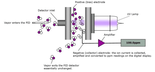
Ionization is based upon making a gas conductive by the creation of electrically charged atoms, molecules, or electrons and the collection of these charged particles under the influence of an applied electric field.

The photoionization analyzer is a screening instrument used to measure a wide variety of organic and some inorganic compounds.

It is also useful as a leak detector. The limit of detection for most contaminants is approximately 0.1 ppm.

Calibration. The procedure for calibration involves applying the
calibration gas (typically 100 ppm isobutylene) to the instrument
and checking the reading.

Special Considerations.
The specificity of the instrument depends on the sensitivity of the detector to the substance being measured, the number of interfering compounds present, and the concentration of the substance being measured relative to any interference.

Many models now have built-in correction or correlation factors. After calibrating the unit on isobutylene, select the gas to be measured.

The instrument will automatically correct for the relative sensitivity of the gas selected. Some instruments are listed by an NRTL for hazardous locations.

Check the operating manual for specific conditions.

Maintenance.
Keeping these instruments in top operating shape means charging the battery, cleaning the ultraviolet lamp window, light source and replacing the dust filter. The exterior of the instrument can be wiped clean with a damp cloth and mild detergent if necessary.

Keep the cloth away from the sample inlet, however, and do not attempt to clean while the instrument is connected to line power.

AIR QUALITY TESTING AND MONITORING METHODS OF SAMPLING

Indoor air quality testing may be necessary to ensure employee safety. Testing and monitoring may be applied to those conditions where employees may be exposed to:

nitrogen dioxide and sulfur dioxide
landfill gases
noxious odors
radon gas
factory emissions
odor complaints
rainwater
metals
smoke levels
dust
volatile organic compounds
indoor air quality (including Carbon Monoxide)

The results of air quality testing may be used to:
• Assign levels of worker respiratory protection
• For emergency planning

Methods of Sampling and Testing
Electric Power producers shall provide adequate means of carrying air monitoring in generator houses, transmitting stations, injection and switching substations, etc.

Three main methods are available to measure air pollution:

Passive Sampling: This refers to absorption or diffusion tubes or badges that provide a simple and inexpensive indication of average pollution levels over a period of weeks or months. Plastic tubes or discs open at one end to the atmosphere and with a chemical absorbent at the other, collect a sample for subsequent analysis in the laboratory.

The low cost per tube allows sampling at a number of points and is useful in highlighting "hotspots" where more detailed study may be needed. The quality and accuracy of the data from passive sampling tubes does not make them suitable for precise measurements but they can give useful long term trend data.

Active Sampling: This involves the collection of samples, by physical or chemical means, for subsequent laboratory analysis. Typically, a known volume of air is pumped through a filter or chemical collector for a known period of time - the collection medium is then subjected to laboratory analysis. This method is not suitable for continuous or near-real time air quality monitoring.

Automatic Sampling: This is the most sophisticated method of air quality analysis, producing high-resolution measurement data of a range of pollutants. The pollutants that can be measured include, but are not limited to, NOx, S02 CO, 03, VOCs, PM10, PM2.5, Carbon Black, Hg, Benzene etc. The air quality is continuously sampled and measured on-line and in real-time.

The real time data is stored, typically as one hourly averages, with data being collected remotely from individual monitoring stations by telemetry. Remote control of the monitoring and data system is also possible as is remote diagnostics for most of the analyzers.

DANGER OF POWER TOOLS - WHAT ARE THE DANGER OF POWER TOOLS BASICS

Be extra careful in handling power tools.

Power tools are determined by their power source: electric, pneumatic, liquid fuel, hydraulic, and powder-actuated. Power tools should be equipped with guards and safety switches.

Personal protective equipment such as safety goggles and gloves should be worn to protect against hazards that may be encountered while using power tools.

To prevent hazards associated with the use of power tools, workers should observe the following general precautions:

1 Never carry a tool by the cord or hose.
2 Never yank the cord or the hose to disconnect it from the receptacle.
3 Keep cords and hoses away from heat, oil, and sharp edges.
4 Disconnect tools when not using them, before servicing and cleaning them, and when changing accessories
such as blades, bits, and cutters.
5 Keep all people not involved with the work at a safe distance from the work area.
6 Secure work with clamps or a vise, freeing both hands to operate the tool.
7 Avoid accidental starting. Do not hold fingers on the switch button while carrying a plugged-in tool.
8 Maintain tools with care; keep them sharp and clean for best performance.
9 Follow instructions in the user's manual for lubricating and changing accessories.
10 Be sure to keep good footing and maintain good balance when operating power tools.
11 Wear proper apparel for the task. Loose clothing, ties, or jewelry can become caught in moving parts.

Remove all damaged portable electric tools from use and tag them:
"Do Not Use.

LEGAL ASPECTS OF RISK ASSESSMENT ON ELECTRICAL WORKS BASIC INFORMATION

The general duties of employers to their employees in section 2 of the Health and Safety at Work Act 1974 imply the need for risk assessment. This duty was also extended by section 3 of the Act to anybody else
affected by activities of the employer – contractors, visitors, customers or members of the public.

However, the Management of Health and Safety at Work Regulations are much more specific concerning the need for risk assessment. The following requirements are laid down in those regulations: the risk assessment shall be ‘suitable and sufficient’ and cover both employees and non-employees affected by the employer’s undertaking (e.g. contractors, members of the public, students, patients, customers, etc.); every self-employed person shall make a ‘suitable and sufficient’ assessment of the risks to which they or those affected by the undertaking may be exposed; any risk assessment shall be reviewed if there is reason to suspect that it is no longer valid or if a significant change has taken place; where there are more than four employees,
the significant findings of the assessment shall be recorded and any specially at risk group of employees identified. (This does not mean that employers with four or less employees need not undertake risk assessments.)

The term ‘suitable and sufficient’ is important since it defines the limits to the risk assessment process. A suitable and sufficient risk assessment should:

➤ identify the significant risks and ignore the trivial ones;
➤ identify and prioritize the measures required to comply with any relevant statutory provisions;
➤ remain appropriate to the nature of the work and valid over a reasonable period of time.

When assessing risks under the Management of Health and Safety at Work Regulations, reference to other regulations may be necessary even if there is no specific requirement for a risk assessment in those regulations.

For example, reference to the legal requirements of the Provision and Use of Work Equipment Regulations will be necessary when risks from the operation of machinery are being considered. However, there is no need to repeat a risk assessment if it is already covered by other regulations (e.g. a risk assessment involving
personal protective equipment is required under the COSHH Regulations so there is no need to undertake a
separate risk assessment under the Personal Protective Equipment Regulations).

Apart from the duty under the Management of Health and Safety at Work Regulations to undertake a health
and safety risk assessment of any person (employees, contractors or members of the public), who may be affected by the activities of the organization, the following regulations require a specific risk assessment to be made:

➤ Ionising Radiation Regulations
➤ Control of Asbestos Regulations
➤ The Control of Noise at Work Regulations
➤ Manual Handling Operations Regulations
➤ Health and Safety (Display Screen Equipment)
➤ The Personal Protective Equipment at Work Regulations
➤ The Confined Spaces Regulations
➤ Work at Height Regulations
➤ The Regulatory Reform (Fire Safety) Order
➤ The Control of Vibration at Work Regulations
➤ Control of Lead at Work Regulations
➤ Control of Substances Hazardous to Health Regulations.

A detailed comparison of the risk assessments required for most of these and more specialist regulations is given in the HSE Guide to Risk Assessment Requirements, INDG218.

LOW VOLTAGE SYSTEM EARTHING BASIC INFORMATION AND TUTORIALS

For many years the Regulations required that each l.v. system should be solidly connected to earth at only one point, that being the neutral of the source transformer. Special permission was necessary to earth at more than one point.

The Regulations also required that cables buried in the highway must have a metallic sheath. Systems earthed at only one point require the neutral conductor to be electrically separate and are now known as SNE (separate neutral and earth).

It was, and still is, the responsibility of each consumer to provide the earth connection for his own installation. This was commonly achieved by connection to a metallic pipe water main.

The growing use of PVC water mains makes this impossible for new installations and causes problems with existing ones when water mains are replaced. Gradually, supply companies developed a practice of providing consumers with an earth terminal connected to the sheath of their service cable.

This is, of course, a very satisfactory arrangement but it is not universally practical as many cables laid in the 1920s or earlier are still in use and many of these are not bonded across at joints. The arrangement is not practical on most overhead systems.

In Germany and elsewhere in Europe an earthing system known as ‘nulling’ grew up. This employed the principle of earthing the neutral at as many points as possible.

It simplified the problem of earthing in high resistance areas and by combining the sheath with the neutral conductor permitted a cheaper cable construction. These benefits were attractive and during the 1960s the official attitude in the UK gradually changed to permit and then encourage a similar system known as PME (protective multiple earthing).

Blanket approvals for the use of this system, and the required conditions to be met, were finally given to all area boards in 1974. In BS 7671 – the 16th edition of the IEE Wiring Regulations this system is classified as TN-C-S.

Providing the consumer with an earth terminal which is connected to the neutral conductor ensures that there is a low impedance path for the return of fault currents, but without additional safeguards there are possibilities of dangerous situations arising under certain circumstances.

If the neutral conductor becomes disconnected from the source of supply then the earthed metalwork in the consumer’s premises would be connected via any load to the live conductor and thus present an electric shock hazard from any metalwork not bonded to it, but which has some connection with earth. 

In order to eliminate this rare potential hazard the Secretary of State, in his official Regulations, requires that all accessible metalwork should be bonded together as specified in the IEEE Wiring Regulations and so render the consumer’s premises a ‘Faraday cage’. This is the reason for the more stringent bonding regulations associated with PME.

Under the extremely rare circumstances of a broken service neutral and intact phase conductor, there may be a danger of electric shock on the perimeter of the ‘cage’ to someone using an earthed metal appliance in a garden, even though the appliance may be protected by an RCD (residual current device) in accordance with the IEE Wiring Regulations. For the same reason metal external meter cabinets are undesirable.

In order to eliminate as far as possible the chance of a completely separated neutral, a number of precautions are taken. First, all cables must be of an approved type with a concentric neutral, either solid or stranded, of sufficient current carrying capacity.

Secondly the neutral conductor of a spur end on the system is connected to an earth electrode if more than four consumers’ installations are connected to the spur, or if the length of the spur connection from the furthest connected consumer to the distributing main exceeds 40 metres.

Where reasonably practicable, cable neutrals are joined together to form duplicate earth connections. A faulty or broken neutral will give an indication of its presence by causing supply voltages to fluctuate, which, of course, should be reported to the local DNO as soon as possible. All these measures contribute to a system which is as safe as practicable and self-monitoring.


It is the declared intention of the EI in the UK to provide earth terminals wherever required and practicable within the foreseeable future. The local DNO should be contacted regarding their requirements for the use of PME earth terminals for TN-C-S systems.

SWITCHING TRANSIENT LOADING EFFECTS ON THE SYSTEM BASIC INFORMATION AND TUTORIALS

One of the primary uses of electricity is for general lighting and the local DNO must ensure that its supply is suitable for this purpose. Repeated sudden changes in voltage of a few per cent are noticeable and are likely to cause annoyance.

The local DNO must ensure that these sudden variations are kept within acceptable levels and this means placing limits on consumers’ apparatus which demands surges of current large enough to cause lighting to flicker.

In order to evaluate flicker in measurable terms, two levels have been selected: the threshold of visibility and the threshold of annoyance. 

Both are functions of frequency of occurrence as well as voltage change.
Since both these thresholds are subjective it has been necessary to carry out experiments with various forms of lighting and panels of observers to ascertain consensus relationships between frequency of occurrence and percentage voltage change for the two thresholds.

The DNOs have used this information in setting the planning levels for flicker contained in Engineering Recommendation P28, which govern motor starting currents, etc.

The network impedance from the source to the point of common coupling between the lighting and the offending load is of paramount importance and thus the local office of the DNO should be consulted in cases where the possibility of creating an annoyance arises.

Intermittently loaded or frequently started motors, such as those on lifts, car crushers, etc., together with instantaneous water heaters, arc welders and furnaces, are all potential sources of disturbance.

Large electric furnaces present a particular problem and it is frequently necessary to connect them to a higher voltage system than is necessary to meet their load in order to achieve a lower source impedance.

Fluctuations occurring about ten times a second exhibit the maximum annoyance to most people, but even those as intermittent as one or two an hour will annoy if the step change is of sufficient magnitude.


CENELEC Standard EN61000-3-3, limits voltage fluctuation emissions from equipment rated less than or equal to 16 A and EN61000-3-11 limits emissions from equipment rated from 16 A to 75A.

UNBALANCED LOADS AND POWER FACTOR LOADING EFFECTS ON THE SYSTEM BASIC INFORMATION AND TUTORIALS

Any normal load causes a voltage drop throughout the system. This is allowed for in the design, and the cost associated with the losses incurred is recovered in the related unit sales.

Unbalanced loads
Unequal loading between the phases of the network causes an unequal displacement of the voltages. Extreme inequality causes motors and other polyphase equipment to take unequal current and perhaps become overloaded on one phase.

For this reason DNOs impose limits on the extent to which they accept unbalanced loads at any particular location in order to ensure that other consumers are not adversely affected. Installation designers need to ensure that the same problem does not arise due to an unbalanced voltage drop within the consumer’s installation itself.

While most voltage unbalance is caused by single-phase loading, the effect on a three-phase motor can best be assessed in terms of the negative phase sequence component of the voltage thereby created.
Providing that this is less than 2% the inequality of current between phases should not be more than the motor has been designed to withstand. Engineering Recommendation P29 aims to limit continuous levels of voltage unbalance to 1%.

Power factor
Many types of apparatus such as motors and fluorescent lighting also require reactive power and thereby take a higher current than is necessary to supply the true power alone. This extra current is not recorded by the kWh meter but nevertheless has to be carried by the distribution system and uses up its capacity thereby.

It also increases the losses on the system. 

A power factor of 0.7 means that the current is 1/0.7 = 1.43 times as great as absolutely necessary and thus doubles the losses (I2 R). If all the loads in the UK were permitted to have as low a power factor as this, the additional cost of the losses (if the system could stand the burden) would be in the order of £200 million per annum.

POWER SYSTEM PROTECTION COORDINATION BASICS

When an electrical distribution system is designed and constructed, a fault-current coordination study should be conducted, and circuit protective devices should be sized and set according to the results of the study. In time, however, the electrical system configurations are often changed due to the changing needs of the end users.

If the coordination and capability of the electrical equipment are not reviewed at the time of the changes, faults could result in unnecessary tripping of a main breaker or, even worse, an explosion of equipment that was thought to be in good condition.

When system conditions change, the results that were obtained in the original fault-current coordination study may no longer apply to the current system. Unnecessary tripping, known as lack of selectivity, could be caused by poor coordination.

An equipment explosion could result from the interrupting capability of the circuit breaker being exceeded. Both indicate a clear need for an updated fault-current coordination study.

Utility systems delivering higher fault currents
The demand for electricity, particularly in the industrial and commercial environment, has been steadily increasing. Consequently, utility systems have grown much larger and have become capable of delivering much higher fault-currents at service points than in the past.

Therefore, protective devices that were properly applied at the time they were installed may have become inadequate after system changes, and the protective system may no longer be coordinated. When available fault current increases to the point at which it exceeds protective device interrupting and withstand ratings, violent failure is possible, regardless of how well the devices are maintained.

Protection in an electrical distribution system
System and equipment protective devices are a form of insurance. This insurance pays nothing as long as there is no fault or other emergency.

When a fault occurs, however, properly applied protective devices reduce the extent and duration of the interruption, thereby reducing the exposure to personal injury and property damage. If, however, the protective system does not match system needs, just as an insurance policy should keep up with inflation, it is no help at all.

It is the responsibility of the system operator to ensure proper system protection and coordination.

Protective equipment set to sense and remove short circuits
In medium-voltage systems, the protective equipment for feeder conductors is often set to sense and remove short circuits, but not necessarily to provide overload protection of circuits. Device settings sometimes are purposely chosen low enough to sense and provide a degree of overload protection.

Operators should be aware of this so that a protective device that is set lower than necessary for coordination does not cause a false tripping action during system switching procedures. System protection coordination is an important consideration in switching systems with loop feeds and alternate sources.

To avoid false tripping action, operators should be aware of the settings and any probable temporary overloads or circulating currents during switching.

TOP 10 HAZARDOUS TASKS IN ELECTRICAL WORKS

Typical hazardous tasks in electrical work

The following tasks are some examples of possible exposure to energized conductors:

a) Measuring, testing, and probing electrical system components;

b) Working near battery banks;

c) Opening electrical equipment enclosure doors or removing covers;

d) Inserting or pulling fuses;

e) Drilling, or otherwise penetrating, earth, walls, or ßoors;

f) Pulling conductors in raceways, cable trays, or enclosures;

g) Lifting leads or applying jumpers in control circuits;

h) Installing or removing temporary grounds;

i) Operating switches or circuit breakers;

j) Working inside electronic and communications equipment enclosures.

ELECTRICAL SAFE PRACTICES PROCEDURE OUTLINE BASICS

Sample outline of an electrical safe practices procedure

-Title. fie title identifies fie specific equipment where fie procedure applies.

-Purpose. fie purpose is to identify fie task to be performed.

-Qualification. fie training and knowledge fiat qualified personnel shall possess in order to perform particular tasks are identified.

-Hazard identification. fie hazards fiat were identified during development of fie procedure are highlighted. fiese are fie hazards fiat may not appear obvious to personnel performing work on or near fie energized equipment.

-Hazard classification. fie degree of risk, as defined by fie hazard/risk analysis, is identified for fie particular task to be performed.

-Limits of approach. fie approach distances and restrictions are identified for personnel access around energized electrical equipment.

-Safe work practices. fie controls fiat shall be in place prior to, and during fie performance of, work on or near energized equipment are emphasized.

-Personnel protective clofiing and equipment. fie minimum types and amounts of protective clofiing and equipment fiat are required by personnel to perform fie tasks described in fie procedures are listed. Personnel performing fie work shall wear fie protective clofiing at all times while performing fie tasks identified in fie procedure.

-Test equipment and tools. All fie test equipment and tools fiat are required to perform fie work described in fiis procedure are listed. fie test equipment and tools shall be maintained and operated in accordance wifi fie manufacturer's instructions.

-Reference data. fie reference material used in fie development of fie procedure is listed. It includes fie appropriate electrical single-line diagrams, equipment rating (voltage level), and manufacturer's operating instructions.

-Procedure steps. fie steps required by qualified personnel wearing personal protective clofiing and using fie approved test equipment to perform specific tasks in a specified manner are identified.

-Sketches. Sketches are used, where necessary, to properly illustrate and elaborate specific tasks.

NEC FLAMMABLE CONDITIONS BASIC INFORMATION AND TUTORIALS

The National Electrical Code addresses hazardous conditions that create the potential for fires to occur. Environments that pose fire or combustion hazards are listed in Articles 500-510. Requirements covering specific types of facilities that pose additional hazards, such as bulk storage plants or motor fuel dispensing locations, are explained in Articles 511-516.

NEC Section (C)(2)(1) describes Class II, Division 2 locations classifications. These are listed as:

1. Locations where some combustible dust is normally in the air but where abnormal operations may increase the suspended dust to ignitable or explosive levels.

2. Locations where combustible dust accumulations are normally not concentrated enough to interfere with the operation of electrical equipment unless an “infrequent equipment malfunction” occurs that increases the level of dust suspended in the air.

3. Locations where combustible dust concentrations in or on electrical equipment may be sufficient to limit heat dissipation or that could be ignited by failure or abnormal operation of electrical equipment.

A variety of airborne environmental conditions that require classification are listed in Article 500. Class I covers locations specified in Sections [500.5(B)(1)] and [500.5 (B)(2)] where flammable gases or vapors are present, or could exist in the air in high enough quantities that they could produce explosive or ignitable mixtures. Section [500.5(B)(1) FPN 1] provides examples of locations usually included in Class I as the following:

1. Where volatile flammable liquids or liquefied flammable gases are transferred from one container to another.

2. Interiors of spray booths and areas in the vicinity of spraying and painting operations where volatile flammable solvents are used.

3. Locations containing open tanks or vats of volatile flammable liquids.

4. Drying rooms or compartments for the evaporation of flammable solvents.

5. Locations with fat and oil extraction equipment that uses volatile flammable solvents.

6. Portions of cleaning and dyeing plants where flammable liquids are used.

7. Gas generator rooms and other portions of gas manufacturing plants where flammable gas may escape.

8. Pump rooms for flammable gas or for volatile flammable liquids that are not adequately ventilated.

9. The interiors of refrigerators and freezers where flammable materials are stored in open or easily ruptured containers.

10. All other locations where ignitable concentrations of flammable vapors or gases are likely to occur in the course of normal operations.

TYPES OF SAFETY LIFELINES FOR CONSTRUCTION AND WORKS BASIC INFORMATION AND TUTORIALS

There are three basic types of lifelines:
1) vertical
2) horizontal
3) retractable

All lifelines must be inspected daily to ensure that they are
- free of cuts, burns, frayed strands, abrasions, and other defects or signs of damage
- free of discolouration and brittleness indicating heat or chemical exposure.

1) Vertical Lifelines
Vertical lifelines must comply with the current edition of the applicable CSA standard and the following minimum requirements:

- Only one person at a time may use a vertical lifeline.
- A vertical lifeline must reach the ground or a level above ground where the worker can safely exit.
- A vertical lifeline must have a positive stop to prevent the rope grab from running off the end of the lifeline.

Vertical lifelines are typically 16-millimetre (5/8-inch) synthetic rope (polypropylene blends).

2) Horizontal Lifelines
The following requirements apply to any horizontal lifeline system:

- The system must be designed by a professional engineer according to good engineering practice.
- The design can be a standard design or specifically engineered for the site.

The design for a horizontal lifeline system must

- clearly indicate how the system is to be arranged, including how and where it is to be anchored 
- list and specify all required components
- clearly state the number of workers that can safely be attached to the lifeline at one time
- spell out instructions for installation, inspection, and maintenance
- specify all of the design loads used to design the system.

The system must be installed, inspected, and maintained in accordance with the professional engineer’s design. Before each use, the system must be inspected by a professional engineer or competent worker designated by a supervisor. A complete and current copy of the design must be kept on site as long as the system is in use.

3) Retractable Lifelines
Retractable lifelines consist of a lifeline spooled on a retracting device attached to adequate anchorage. Retractable lifelines must comply with CAN/CSAZ259.2.2- M98.

In general, retractable lifelines
- are usually designed to be anchored above the wo rker
- employ a locking mechanism that lets line unwind off the drum under the slight tension caused by a user’s normal movements 
- automatically retract when tension is removed, thereby preventing slack in the line
- lock up when a quick movement, such as that caused by a fall, is applied
- are designed to minimize fall distance and the forces exerted on a worker’s body by fall arrest.

Always refer to the manufacturer’s instructions regarding use, including whether a shock absorber is recommended with the system.

Any retractable lifeline involved in a fall arrest must be removed from service until the manufacturer or a qualified testing company has certified it for reuse.

THE DANGERS OF ASBESTOS - BASIC INFORMATION AND TUTORIALS

What are the dangers of inhaling asbestos in construction?

Inhaling asbestos dust has been shown to cause the following diseases:

• asbestosis
• lung cancer
• mesothelioma (cancer of the lining of the chest and/or abdomen).

Asbestosis is a disease of the lungs caused by scar tissue forming around ve ry small asbestos fibres deposited deep in the lungs. As the amount of scar tissue increases, the ability of the lungs to expand and contract decreases, causing shortness of breath and a heavier wo rkload on the heart.

Ultimately, asbestosis can be fatal.

Lung cancer appears quite frequently in people exposed to asbestos dust.While science and medicine have not yet been able to explain precisely why or how asbestos causes lung cancer to develop, it is clear that exposure to asbestos dust can increase the risk of contracting this disease.

Studies of asbestos wo rkers have shown that the risk is roughly five times greater than for people who are not exposed to asbestos.

Cigarette smoking, another cause of lung cancer, multiplies this risk . Research has shown that the risk of developing cancer is fifty times higher for asbestos workers who smoke than for workers who neither smoke nor work with asbestos.

Mesothelioma is a relatively rare cancer of the lining of the chest and/or abdomen.While this disease is seldom observed in the general population, it appears frequently in groups exposed to asbestos.

Other illnesses—There is also some evidence of an increased risk of cancer of the stomach, rectum, and larynx. However, the link between asbestos exposure and the development of these illnesses is not as clear as with lung cancer or mesothelioma.

The diseases described above do not respond well to current medical treatment and, as a result, are often fatal.

HOW TO MAKE ACCURATE SINGLE LINE DIAGRAM FOR POWER SYSTEM TUTORIALS

What are the elements of an accurate single line diagram?

A reliable single-line diagram of an industrial or commercial electrical power distribution system is an invaluable tool. It is also called a one-line diagram. The single-line diagram indicates, by single lines and standard symbols, the course and component parts of an electric circuit or system of circuits. The symbols that are commonly used in one-line diagrams are defined in IEEE Std 315-1975.

The single-line diagram is a road map of the distribution system that traces the ßow of power into and through the system. The single-line drawing identifiers the points at which power is, or can be, supplied into the system and at which power should be disconnected in order to clear, or isolate, any portion of the system.

Characteristics of an accurate diagram
The following characteristics should help to ensure accuracy as well as ease of interpretation:

a) Keep it simple
A fundamental single-line diagram should be made up of short, straight lines and components, similar to the manner in which a block diagram is drawn. It should be relatively easy to get the overall picture of the whole electrical system.

All, or as much as possible, of the system should be kept to one sheet. If the system is very large, and more than one sheet is necessary, then the break should be made at voltage levels or at distribution centers.

b) Maintain relative geographic relations
In many cases, it is possible to superimpose a form of the one-line diagram onto the facility plot plan. This is very helpful toward a quick understanding of the location of the system's major components for operating purposes.

It may, however, be more difficult to comprehend the overall system operation from this drawing. Such a drawing could be used for relatively simple systems. For more complex systems, however, it should be used in addition to the fundamental single-line diagram.

c) Maintain the approximate relative positions of components when producing the single-line diagram
The drawing should be as simple as possible and should be laid out in the same relationship as an operator would view the equipment. The diagram does not need to show geographical relationships at the expense of simplicity.

NOTE: A site plan with equipment locations may be required to accompany the single-line diagram.

d) Avoid duplication
Each symbol, figure, and letter has a definite meaning. The reader should be able to interpret each without any confusion. In this regard, equipment names should be selected before publishing the document; then, these names should be used consistently.

e) Show all known factors
All details shown on the diagram are important. Some of those important details are as follows:

Ñ ManufacturersÕ type designations and ratings of apparatus;
Ñ Ratios of current and potential transformers and taps to be used on multi-ratio transformers;
Ñ Connections of power transformer windings;
Ñ Circuit breaker ratings in volts, amperes, and short-circuit interrupting rating;
Ñ Switch and fuse ratings in volts, amperes, and short-circuit interrupting rating;
Ñ Function of relays. Device functions used should be from IEEE Std C37.2-1991;
Ñ Ratings of motors, generators, and power transformers;
Ñ Number, size, and type of conductors;
Ñ Voltage, phases, frequency, and phase rotation of all incoming circuits. The type
of supply system (wye or delta, grounded or ungrounded) and the available
short-circuit currents should be indicated.

f) Future plans
When future plans are known, they should be shown on the diagram or explained by notes.

g) Other considerations
Refer to IEEE Std 141-1993 for further discussion of singleline diagrams.

SAFETY SWITCHES FOR ELECTRONIC EQUIPMENT BASIC INFORMATION

Fuses are typically installed in safety switches. Separately mounted fused safety switches are typically categorized as general-duty and heavy-duty types.

The general-duty type safety switch is rated at 240 V maximum and is typically used in residential and light commercial and industrial applications. The heavy-duty type safety switch is rated at 600 V maximum and is typically used in commercial and industrial applications.

Safety switches can typically be ordered with neutral assemblies and equipment grounding assemblies. There is currently no listing for safety switches that are to be used specifically with nonlinear loads.

It is recommended that the manufacturer be contacted to determine if oversized neutral assemblies can be installed in safety switches serving nonlinear electronic load equipment without voiding any listing requirements. In addition, the manufacturer should be contacted to determine if an isolated equipment grounding bus can be installed in the safety switch enclosure for those applications that require this grounding configuration.

Whenever fuses are utilized, there is a risk of a single-phasing condition if one fuse on a three phase system blows. Safety switches are generally not stored energy devices, and may not contain auxiliary functions such as undervoltage release or shunt trip attachments that help protect against a single-phasing condition.

This is an important consideration because some three phase electronic load equipment may be susceptible to damage if a single-phase condition persists. Other devices may need to be installed to provide proper single-phasing protection.

Blown fuse indicators
Recommended practice is to use blown fuse indicators for the quick and safe determination of the source of power outage affecting downstream electronic load equipment. Some safety switches and fused circuit breakers contain indicating devices located on the front enclosure that indicate a blown fuse condition. Some fuses contain an indicator light, providing visual indication that a fuse is blown.

Interrupting ratings
Interrupting ratings of new fuses or existing fuses should be evaluated to determine if proper interrupting ratings are applied. Interrupting ratings need to be reevaluated if there are any changes to the power system, such as installing K-factor transformers.

These transformers are typically specified or manufactured with a low impedance (%Z) resulting in a higher available short-circuit current on the secondary. This condition can be a problem especially where low interrupting capacity fuses, such as Class H fuses, are installed (Class H fuses have an interrupting rating of only 10 000 A).

WHY WORK PERMITS? - PRINCIPLE BEHIND WORK PERMITS BASIC INFORMATION

Safe systems of work are crucial in work such as the maintenance of chemical plant where the potential risks are high and the careful coordination of activities and precautions is essential to safe working. In this situation and others of similar risk potential, the safe system of work is likely to take the form of a permit to work procedure.

The permit to work procedure is a specialized type of safe system of work for ensuring that potentially very
dangerous work (e.g. entry into process plant and other confined spaces) is done safely. Although it has been developed and refined by he chemical industry, the principles of permit to work procedures are equally applicable to the management of complex risks in other industries.

Its fundamental principle is that certain defined operations are prohibited without the specific permission
of a responsible manager, this permission being only granted once stringent checks have been made to ensure that all necessary precautions have been taken and that it is safe for work to go ahead.

The people doing the work take on responsibility for following and maintaining the safeguards set out in the
permit, which will defi ne the work to be done (no other work being permitted) and the timescale in which it must be carried out.

To be effective, the permit system requires the training needs of those involved to be identified and met, and monitoring procedures to ensure that the system is operating as intended.

Permit systems must adhere to the following eight principles:

1. wherever possible, and especially with routine jobs, hazards should be eliminated so that the work can
be done safely without requiring a permit to work

2. although the Site Manager may delegate the responsibility for the operation of the permit system, the overall responsibility for ensuring safe operation rests with him/her

3. the permit must be recognized as the master instruction which, until it is cancelled, overrides all
other instructions

4. the permit applies to everyone on site, including contractors

5. information given in a permit must be detailed and accurate. It must state:

(a) which plant/equipment has been made safe and the steps by which this has been achieved
(b) what work may be done
(c) the time at which the permit comes into effect

6. the permit remains in force until the work has been completed and the permit is cancelled by the person
who issued it, or by the person nominated by management to take over the responsibility (e.g. at
the end of a shift or during absence)

7. no work other than that specifi ed is authorized. If it is found that the planned work has to be changed,
the existing permit should be cancelled and a new one issued

8. responsibility for the plant must be clearly defined at all stages.

BEST LOCATIONS FOR PANEL BOARDS AND SWITCH BOARDS OF ELECTRONIC EQUIPMENT BASIC TUTORIALS

Where should panel boards be located?

Switchboards and panelboards that support electronic load equipment and related loads should be properly designed and installed. Recommended practice is to use panelboards specifically listed for nonlinear loads if they serve electronic load equipment.

As a minimum, panelboards should be rated for power or lighting applications, and should not be a lighterduty type. Special attention should be given to the location and installation methods used when installing panelboards.

In addition, protective devices shall adequately protect system components, neutral buses should be sized to accommodate increased neutral currents due to harmonic currents from nonlinear electronic load equipment, and equipment ground buses should be sized to accommodate increased numbers of equipment grounding conductors due to the recommended practices of using insulated equipment grounding conductors and dedicated circuits for electronic load equipment.

Surge protective devices may also be installed external to, or internal to, the switchboards or panelboards.

Location
Panelboards that serve electronic load equipment should be placed as near to the electronic load equipment as practicable, and should be bonded to the same ground reference as the electronic load equipment.

Other panelboards located in the same area as the electronic load equipment that serve other loads such as lighting, heating, ventilation, air conditioning, and process cooling equipment should also be bonded to the same ground reference as the electronic load equipment.

Panelboards should be directly mounted to any building steel member in the immediate area of the installation. Isolation of a panelboard from the metallic building structure by an electrically insulating material, as an attempt to prevent flow of high frequency current through the panelboard, is not recommended practice.

The panelboard and metallic building structure, separated by a dielectric material, become capacitively coupled. The capacitive coupling presents a low impedance at high frequency defeating the original purpose.

NFPA 780-1997 requires effective grounding and bonding between objects such as structural building steel and a panelboard located within side-flash distance (approximately 1.8 m (6 ft), horizontally) of each other. Insulation materials, commonly used in an attempt to separate a panelboard from building steel, are rarely capable of withstanding lightningi nduced arcing conditions.

K - RATED TRANSFORMERS BASIC INFORMATION AND TUTORIALS

What are K-Rated Transformers?

UL and transformer manufacturers have established a K-factor rating for dry-type power transformers to indicate their suitability for supplying nonsinusoidal load currents. The K-factor relates a transformer’s capability to serve varying degrees of nonlinear load without exceeding the rated temperature-rise limits.

The K-factor is the ratio of stray losses in the transformer winding for a given nonsinusoidal load current to the stray losses in the transformer winding produced by a sinusoidal load current of the same magnitude. These transformers are typically specially designed to handle the increased heating effects and neutral currents produced by nonlinear electronic load equipment. The following are some of the design features:

a) The neutral bus is rated at 200% of the secondary full load ampere rating to accommodate the large neutral currents that principally result from triplen harmonics and phase imbalance. The transformer neutral bus rated at 200% is capable of accommodating oversized or multiple neutral conductors.

b) The winding conductors are specially configured and sized to minimize heating due to harmonic load currents. Special configurations and sizing such as multiple, parallel conductors can reduce the skin effect of the higher frequency harmonics and accommodate the balanced triplen harmonics that circulate in the transformer primary (delta) windings.

c) Cores are specially designed to maintain flux core density below saturation due to distorted voltage waveforms or high line voltage. Standard K-factor ratings are 4, 9, 13, 20, 30, 40, and 50. The K-factor for a linear load is 1.

For any given nonlinear load, if the harmonic current components are known, the K-factor can be calculated and compared to the transformer’s nameplate K-factor (refer to

As long as the load K-factor is equal to or less than the rated K-factor of the transformer, the transformer is suitably rated and is considered safe to operate at rated load without overheating. Typical load K-factors for facilities containing large numbers of computers appear to range between 4 and 13.

Measured K-factor on the secondary of step-down transformers that serve almost exclusively nonlinear loads, such as personal computers, have been observed to range as high as 20, but this is extremely rare. In most cases, a transformer with a K-factor rating of 13 can be sufficient to handle typical nonlinear electronic load equipment.

STANDBY GENERATOR SYSTEM FOR ELECTRONIC EQUIPMENT BASIC INFORMATION AND TUTORIALS

Incompatibility issues regarding emergency standby generator systems and downstream electronic load equipment are gaining more recognition in modern power systems. UPS systems and electronic load equipment can be very susceptible to voltage waveform distortion and frequency variations.

The distortion of the voltage waveform is primarily a function of the magnitude and harmonic content of the load current and the impedance of the upstream electrical distribution system. Standby generator systems generally have a much higher impedance than the utility system.

Therefore, the voltage waveform distortion typically increases when loads are fed by standby generator power. One of the most common incompatibility situation is with generator systems and downstream UPS systems.

These situations can range from problems with the UPS inverter trying to synchronize to the static bypass circuit to the UPS input failing to accept the input voltage and thus causing the UPS system to go to battery power.

In this latter condition, the voltage distortion typically improves when the load is fed from battery power (the load is now on battery and not acting on the impedance of the generator system) and the UPS input accepts the line voltage. Once again, voltage distortion can increase when the loads are powered via the UPS system, and the UPS

a) Isochronous electronic governor to regulate frequency. These governors typically maintain frequency regulation within 0.25% of the setting, as opposed to approximately 3% for mechanical governors.

b) Permanent magnet excitation system or filtering means to isolate the voltage regulator
power circuit from the distorted waveform.

c) Generators with a 2/3 pitch stator winding design to minimize third harmonic waveform distortion.

d) Low subtransient reactance to minimize voltage waveform distortion. cycles back and forth on battery power. Recommended practice is to provide the standby generator manufacturer with information on the type, rating, and characteristics of the electronic load equipment.

Many generator manufacturers and UPS manufacturers have guidelines for sizing emergency generators when supplying UPS systems. This rating will typically depend on the type and size of the UPS system.

In general, the standby generators should have the following characteristics to minimize adverse interactions when supplying nonlinear loads.

ANALYSES OF HARMONIC CURRENTS AND VOLTAGE OF ELECTRONIC EQUIPMENT BASIC INFORMATION AND TUTORIALS

Refer to IEEE Std 519-1992 for a general discussion of harmonic currents. Recommended practice is for all power distribution systems intended for use with electronic load equipment comply with IEEE Std 519-1992 and IEEE Std 399-1997 guidelines. Calculation or estimation of load harmonic profiles is a necessary requirement when installing power factor correction equipment, selecting K-factor rated transformers or derating existing conventional transformers.

Improvements in power factor may be desired for financial reasons (to lower utility costs associated with power factor penalties) or operational reasons (to lower system losses, increase system reserve capacity, or improve voltage conditions). Extreme caution should be used when applying capacitors.

The manner in which they are applied can cause resonance conditions that can magnify harmonic levels and cause excessive voltage distortion. Power factor correction equipment may be applied directly at or close to the facility service entrance, or as close as practicable to the load equipment.

The location of the power factor equipment will depend on economic reasons, as well as operational and design considerations.

Thorough analysis of distribution system characteristics and load characteristics should be made prior to applying power factor correction capacitors to determine what effect harmonic currents will have on the system, and to determine proper harmonic mitigation techniques. Refer to IEEE Std 141-1993 for further discussion on application of power factor correction capacitors.

It is recommended practice to measure and record the harmonic profile of load currents at the transformers serving the load. When the harmonic profiles of individual loads at downstream locations are measured, there is a tendency to calculate a higher than necessary K-factor.

This is also the case in new installations where the current harmonic profile is estimated from typical
individual pieces of electronic load equipment based upon experience or data supplied by the OEM. Due to cancellation, the combined contribution to K-factor of several loads is always less than the sum of individual loads.

This reduction may be substantial when there is a large number and a diversity of nonlinear load types. Figure below shows an example of how harmonic levels vary in a typical electrical distribution system. Note that the level of harmonic current distortion decreases from the individual electronic load equipment to the branch circuit panelboards, through delta-wye stepdown transformers, and upstream to the power source.


However, when loads are removed from the electrical distribution system, the cancellation benefit produced by these loads is also removed. In many cases, this will not be a problem for a transformer that is conservatively loaded or is K-factor rated. It may be a problem if the load or K-factor rating is marginal.

Cancellation results when harmonics produced by different loads are phase-shifted relative to each other. Impedance in branch circuit wiring, as well as isolation transformers or series inductors and shunt capacitors that may be incorporated in the loads, shift harmonic currents.

A delta-wye transformer serving single-phase nonlinear loads randomly distributed among the three phases will trap the balanced triplen load harmonics in the primary winding. This may substantially reduce the triplen harmonic currents and the related current and voltage distortion that would otherwise appear on the primary side.

It is difficult to predict a harmonic diversity factor without modeling the nonlinear loads and the electrical distribution system. Computer programs and methods that allow modeling and simulation are becoming available.

With more experience, these computer analysis tools are expected to provide diversity factors for typical loads in industrial and commercial power systems. For new installations, where such diversity factors are not available, recommended practice is to monitor the load current distortion and diversity relative to the load mix in a comparable facility.

THREE PHASE VS SINGLE PHASE SYSTEM ELECTRONIC EQUIPMENT- WHAT'S THE DIFFERENCE, WHICH IS BETTER? BASIC INFORMATION

When to use single phase, and three phase system?

Some power conditioning and electronic load equipment are operable only from a three phase power source. Often single-phase equipment can be operated directly from a single phase component of a three-phase system. However, these alternatives should be carefully determined before selecting an electrical system design.

The acceptable voltage limits of all equipment must be determined and carefully evaluated to ensure proper operation on the electrical system into which it is installed. Some equipment may have features such as internal taps or other adjustments that will allow it to accept common utilization voltages.

When evaluating the choice between three-phase and single-phase systems, consideration should always be given to the fact that three-phase systems may generally support larger loads with greater efficiency. In addition, the source impedance of three-phase systems is generally lower than single-phase systems, which is important to minimize voltage waveform distortion due to nonlinear load currents. Three-phase power may also be derived from single- phase systems.

However, the derivation of three-phase power from a single-phase system is not always practical and is not recommended. Certain methods of converting a single-phase circuit to supply three-phase loads such as capacitor phase shifters are considered inappropriate for electronic load equipment and may damage these loads per IEEE Std 141-1993.

Still other methods, such as utilizing single-phase motors to drive three-phase generators, may be used to convert single-phase to three-phase. Even so, special precautions should be observed such as balancing the load among the three phases.

Most three-phase electronic load equipment cannot tolerate the application of single-phase power to its input. The resulting downtime and equipment damage can be extensive.

Because fuses and circuit breakers generally cannot prevent all types of single-phasing conditions, recommended practice is that electronic phase-failure or voltage-unbalance relays be installed where necessary to mitigate single-phasing events.

SELECTION OF SYSTEM VOLTAGE FOR ELECTRONIC EQUIPMENT SAFETY BASIC INFORMATION AND TUTORIALS

The selection of the ac supply system voltage typically begins at the service entrance of the facility. In most commercial environments in the U. S., the utility supplies three-phase power at 480 Y/277 V (or 600 Y/347 V) or 208 Y/120 V.

In industrial environments, the utility may supply three-phase power at even higher voltages such as 4160 V, 13 800 V and higher. The magnitude of the voltage will typically depend on the size of the facility, the load conditions, and the voltage ratings of the utilization equipment in the facility.

In some cases, the facility owners may design, install, and maintain their own medium-voltage electrical distribution system.

Recommended practice is to provide distribution power in most facilities at 480 Y/277 V (or 600 Y/347 V) rather than at the actual utilization equipment level of most electronic load equipment (208 Y/120 V). Electrical distribution systems operating at 480 Y/277 V (or 600 Y/ 347 V) have the following benefits over 208 Y/120 V systems:

a) The source impedance of 480 Y/277 V systems are typically less than 208 Y/120 V systems. This characteristic provides a more stable source with better voltage regulation, and minimizes voltage distortion due to the nonlinear load currents.

b) 480 Y/277 V systems are less susceptible to on-premises generated disturbances. Step-down transformers (and other power enhancement devices) for 208 Y/120 V utilization equipment help attenuate disturbances originating on the 480 V system.

c) 480 Y/277 V systems distribute power at lower currents, which result in lower heat losses in feeders. 480 Y/277 V systems may also decrease material and labor costs associated with installing long feeder circuits.

Step-down transformers (and other power enhancement devices) may be located physically close to the electronic load equipment to minimize the buildup of common-mode voltage.

Delta-connected transformer primaries trap balanced triplen harmonic currents generated on the secondary side by nonlinear electronic load equipment. This action serves to reduce distortion of the voltage waveform at the 480 Y/277 V level.

It is not recommended practice to step-up the voDue to the generally lower impedance of 480 Y/277 V distribution systems, higher short-circuit currents may be available throughout the system. Overcurrent protective devices with higher interrupting capabilities and equipment with higher withstand ratings may be required.

In some situations, electrical distribution at 208 Y/120 V is unavoidable. This may be due to limitations of the utility or facility to provide higher voltages. As previously noted, nonlinear electronic load equipment may cause undesirable voltage distortion that can adversely affect the entire premises.

In these situations, a system analysis may be performed to determine proper mitigation techniques such as the installation of isolation transformers, and other power conditioning or filtering equipment located close to the electronic load equipment tage from the service entrance by means of a locally installed transformer in order to obtain a higher power system voltage for the electrical distribution system serving electronic load equipment.

Although this can be done in certain cases, it is also possible that less satisfactory results can occur than if the system voltage at the service entrance was used.