What is Reliability Centered Maintenance?
Reliability-Centered Maintenance (RCM) is the process of determining the most effective maintenance approach. The RCM philosophy employs Preventive Maintenance (PM), Predictive Maintenance (PdM), Real-time Monitoring (RTM), Run-to-Failure (RTF- also called reactive maintenance) and Proactive Maintenance techniques in an integrated manner to increase the probability that a machine or component will function in the required manner over its design life cycle with a minimum of maintenance.
The goal of the philosophy is to provide the stated function of the facility, with the required reliability and availability at the lowest cost. RCM requires that maintenance decisions be based on maintenance requirements supported by sound, technical, and economic justification.
A Brief History of RCM
RCM originated in the Airline industry in the 1960s. By the late 1950s, the cost of maintenance activities in this industry had become high enough to warrant a special investigation into the effectiveness of those activities. Accordingly, in 1960, a task force was formed consisting of representatives of both the airlines and the Federal Aviation Administration (FAA) to investigate the capabilities of preventive maintenance.
The establishment of this task force subsequently led to the development of a series of guidelines for airlines and aircraft manufacturers to use, when establishing maintenance schedules for their aircraft.
This led to the 747 Maintenance Steering Group (MSG) document MSG-1; Handbook: Maintenance Evaluation and Program Development from the Air Transport Association in 1968. MSG-1 was used to develop the maintenance program for the Boeing 747 aircraft, the first maintenance program to apply RCM concepts. MSG-2, the next revision, was used to develop the maintenance programs for the Lockheed L 1011 and the Douglas DC-10.
The success of this program is demonstrated by comparing maintenance requirements of a DC-8 aircraft, maintained using standard maintenance techniques, and the DC-10 aircraft, maintained using MSG-2 guidelines. The DC-8 aircraft has 339 items that require an overhaul, verses only seven items on a DC-10.
Using another example, the original Boeing 747 required 66,000 labor hours on major structural inspections before a major heavy inspection at 20,000 operating hours. In comparison, the DC-8 - a smaller and less sophisticated aircraft using standard maintenance programs of the day required more than 4 million labor hours before reaching 20,000 operating hours.
In 1974 the U.S. Department of Defense commissioned United Airlines to write a report on the processes used in the civil aviation industry for the development of maintenance programs for aircraft. This report, written by Stan Nowlan and Howard Heap and published in 1978, was entitled Reliability Centered Maintenance,5 and has become the report upon which all subsequent Reliability Centered Maintenance approaches have been based.
What Nowlan and Heap found was that many types of failures could not be prevented no matter how intensive the maintenance activities were. Additionally it was discovered that for many items the probability of failure did not increase with age. Consequently, a maintenance program based on age will have little, if any effect on the failure rate.
THE SAFETY-RELATED CASE FOR ELECTRICAL MAINTENANCE
The relationship between safety and preventive maintenance is not a difficult one to establish. Properly designed equipment that is properly installed is well capable of doing its job when it is new.
As equipment ages however, several factors begin to take their toll on electrical equipment.
● Dust, dirt, and other contaminants collect on equipment causing the equipment to overheat and bearings and other moving parts to bind.
● Vibration causes hardware to loosen. Subsequent operations of equipment can cause joints and equipment to fail explosively.
● Heat and age can cause insulation to fail, resulting in shock hazards to personnel.
● Increased loads, motor starting surges, and power quality issues such as harmonics combine to increase the aging process and set the stage for equipment failure.
Unfortunately, the ultimate failure of unmaintained equipment usually occurs when the equipment is needed the most—during electrical faults. Such failures result in arc and blast events that can and do harm workers in the area.
They also result in significant downtime, loss of equipment, and construction cost incurred in rebuilding the equipment. The only way to ensure that electrical equipment continues to operate in an optimal manner is to maintain it so that it stays in factory-new-operating condition.
Regulatory
As discussed above and in previous chapters, the catastrophic failure of electrical equipment creates severe hazards for personnel working in the area. Recognizing this the
Standard for Electrical Safety in the Workplace (NFPA 70E)3 requires that electrical equipment be properly maintained to minimize the possibility of failure.
Relationship of Improperly Maintained Electrical Equipment to the Hazards of Electricity
Improperly maintained equipment may expose workers to any of the three electrical hazards. For example:
1. Improperly maintained tools or flexible cord sets (extension cords) can have frayed insulation which exposes the energized conductors and allows them to contact the worker or the metallic tool the worker is using. The result is an electric shock.
2. Improperly maintained protective devices, such as circuit breakers or fuses, can fail when interrupting an overcurrent. Such a failure is likely to be explosive; consequently, the worker is exposed to electrical arc and electrical blast.
3. Improperly maintained connections can overheat resulting in any of the following:
a. melted insulation, exposed conductors, and the attendant electrical shock hazard
b. fire
c. failed connections resulting in electrical arc and blast
4. Improperly maintained switchgear, motor control centers, or panelboards can fail explosively when an arc occurs internally. This exposes workers to the effects of electrical blast and possibly electrical arc.
ELECTRICAL EMERGENCIES GUIDE - WHAT TO DO IN CASE OF ELECTRICAL EMERGENCIES?
Strong winds, ice or unintentional contact with equipment may cause trees or tree limbs to fall into powerlines. This may cause wires to break and fall to the ground. Should this happen, notify the electric utility company immediately.
A fallen wire can create hazards for workers and the general public. Objects touched by a fallen wire - fences, vehicles, buildings or even the surrounding ground - must be considered energized and should not be touched.
It is impossible to tell simply by looking whether a downed wire is energized. Consider all downed wires energized and dangerous until the electric utility personnel notify you otherwise.
Where a power line has fallen across a vehicle, occupants should remain within the vehicle. If they must leave the vehicle because of a life-threatening situation, such as fire or potential explosion, they should jump clear of the vehicle without touching either the vehicle or wire and the ground at the same time.
Once clear of the vehicle, they should shuffle away, taking small steps and keeping both feet in contact with the ground.
Remember, electricity can be transmitted from the victim to you. If a switch is accessible, shut off the power immediately. Otherwise, stand on a dry surface and pull the victim away with a dry board or rope. Do not use your hands or anything metal.
Use a C02 or dry chemical extinguisher to put out an electrical fire. Water should be used only by trained firefighting personnel. In an emergency involving power lines or electrical equipment, call the electric utility company immediately.
Training Workers
Ensure that workers assigned to operate cranes and other boomed vehicles are specifically trained in safe operating procedures. Also ensure that workers are trained (1) to understand the limitations of such devices as boom guards, insulated lines, ground rods, nonconductive links, and proximity warning devices, and (2) to recognize that these devices are not substitutes for de-energizing and grounding lines or maintaining safe clearance.
Workers should also be trained to recognize the hazards and use proper techniques when rescuing coworkers or recovering equipment in contact with electrical energy. CSA guidelines list techniques that can be used when equipment contacts energized power lines [CSA 1982]. All employers and workers should be trained in cardiopulmonary resuscitation (CPR).
THE USE OF GROUND FAULT CURRENT INTERRUPTER (GFCI) IN SAFE ELECTRICAL SYSTEM
A groundfault circuit interrupter (GFCI) is an electrical device which protects personnel by detecting potentially hazardous ground faults and immediately disconnecting power from the circuit. Any current over 8 mA is considered potentially dangerous depending on the path the current takes, the amount of time exposed to the shock, as well as the physical condition of the person receiving the shock.
GFCIs should be installed in such places as dwellings, hotels, motels, construction sites, marinas, receptacles near swimming pools and hot tubs, underwater lighting, fountains, and other areas in which a person may experience a ground fault.
A GFCI compares the amount of current in the ungrounded (hot) conductor with the amount of current in the neutral conductor. If the current in the neutral conductor becomes less than the current in the hot conductor, a ground fault condition exists.
The missing current is returned to the source by some path other than the intended path (fault current). A fault current as low as 4 mA to 6 mA activates the GFCI and interrupts the circuit.
Once activated, the fault condition is cleared and the GFCI manually resets before power may be restored to the circuit. GFCI protection may be installed at different locations within a circuit.
Direct-wired GFCI receptacles provide a ground fault protection at the point of installation. GFCI receptacles may also be connected to provide GFCI protection at all other receptacles installed downstream on the same circuit. GFCI CBs, when installed in a load center or panelboard, provide GFCI protection and conventional circuit overcurrent protection for all branch-circuit components connected to the CB.
Plug-in GFCls provide ground fault protection for devices plugged into them. Plug-in devices are generally utilized by personnel working with power tools in an area that does not include GFCI receptacles.
HOW GFCI WORKS? THE OPERATING PRINCIPLE OF GFCI
A GFCI compares the amount of current in the ungrounded (hot) conductor with the amount of current in the neutral conductor.
GFCI operation diagram is found below:
THE DECIBEL SCALE - UNDERSTANDING SAFETY NOISE
A sound consists essentially of a moving series of pressure fluctuations, and the normal unit of pressure is the pascal (abbreviated to Pa). However, it is not normal to measure sound in pascals; instead the decibel (abbreviated to dB) scale is used.
The decibel scale is a logarithmic one, which compresses a large range of values to a much smaller range. For example, the range of sound pressures from 0.00002 to 2.0 Pa is represented on the decibel scale by the range 0 to 100 dB. Two justifications are normally given for using a decibel scale.
1. The range of values involved in measuring the amplitude of sound is inconveniently large.
2. The human ear does not respond linearly to different sound levels and the decibel scale relates sound measurement more closely to subjective impressions of loudness.
Neither of these explanations really stands up to scrutiny. We cope with larger ranges of values when measuring other quantities (length and money are just two examples of this). It is certainly true that our ears do not respond linearly to changes in sound pressure. In other words doubling the sound pressure does not double the apparent loudness of a sound.

However, they do not respond linearly to the decibel scale either, so little has been gained in this respect by using a decibel scale. Whatever the original reasons for adopting a decibel scale, it is now used universally, so there is no alternative but to do so.
The use of a logarithmic scale dates from the days before electronic calculators when many calculations were carried out with the help of a book of logarithms, or ‘log’ tables. As a result, logarithms were much more familiar to anyone who needed to carry out calculations regularly.
Many fewer people are nowadays familiar with them. Fortunately, with the help of a calculator, decibel calculations can be carried out without any great understanding of how logarithms work.
In other fields, different logarithms – called natural logarithms and abbreviated to either loge or ln – are used.
In workplace noise calculations, all logarithms will be the more familiar system based on the number 10. They are sometimes called ‘logs to base 10’, abbreviated to log10, log or simply lg.
The decibel scale is a logarithmic one, which compresses a large range of values to a much smaller range. For example, the range of sound pressures from 0.00002 to 2.0 Pa is represented on the decibel scale by the range 0 to 100 dB. Two justifications are normally given for using a decibel scale.
1. The range of values involved in measuring the amplitude of sound is inconveniently large.
2. The human ear does not respond linearly to different sound levels and the decibel scale relates sound measurement more closely to subjective impressions of loudness.
Neither of these explanations really stands up to scrutiny. We cope with larger ranges of values when measuring other quantities (length and money are just two examples of this). It is certainly true that our ears do not respond linearly to changes in sound pressure. In other words doubling the sound pressure does not double the apparent loudness of a sound.
However, they do not respond linearly to the decibel scale either, so little has been gained in this respect by using a decibel scale. Whatever the original reasons for adopting a decibel scale, it is now used universally, so there is no alternative but to do so.
The use of a logarithmic scale dates from the days before electronic calculators when many calculations were carried out with the help of a book of logarithms, or ‘log’ tables. As a result, logarithms were much more familiar to anyone who needed to carry out calculations regularly.
Many fewer people are nowadays familiar with them. Fortunately, with the help of a calculator, decibel calculations can be carried out without any great understanding of how logarithms work.
In other fields, different logarithms – called natural logarithms and abbreviated to either loge or ln – are used.
In workplace noise calculations, all logarithms will be the more familiar system based on the number 10. They are sometimes called ‘logs to base 10’, abbreviated to log10, log or simply lg.
HARD HAT DESIGN - RECOMMENDED BASIS FOR HEAD PROTECTION OF ELECTRICAL WORKERS
An eye injury can put you out of work for days or weeks, but a head injury can put you out of work permanently, and can even be terminal. Think about this seriously for a minute. Your brain is inside your head and it controls everything your body does.
Some worker injuries that have resulted from not wearing a hardhat include permanently blurred vision, memory loss, and lack of coordination. Your neck and spine are connected to your head and an injury to these vital structures can leave you paralyzed for life.
OSHA 1910.135 requires that anytime there is the chance of falling overhead objects, tight construction areas where workers could bump their heads on surrounding objects, or the possibility that a worker’s head could accidentally come in contact with EHs, an employer must make sure that workers wear head protection.
A hardhat’s design includes a suspension harness that provides impact protection and ventilation.

That criteria covers just about any worksite condition.
Hardhats have a hard outer shell and a shock-absorbing lining with a headband and straps that suspend the shell from 1 to 1¼ inches away from your head. The basic design provides ventilation during normal wear and shock absorption in the event of an impact.
When you wear a hardhat, the force of a falling object is transmitted and distributed, reducing the impact by approximately 75%. The force of a falling object can be calculated from the weight of the object and the distance that it falls.
For example, a metal washer falling about 30 feet will generate a force of 6½ pounds on impact! Now imagine that you are pulling wire in a new construction house and someone working on the trusses two stories above you drops his hammer and it hits your hardhat.
This kind of accident has happened more than once, resulting in nothing more than a startled electrician with a few choice words for the carpenter above him. However, without your hardhat to dissipate and absorb that kind of shock, you could end up with a fractured skull or an injury that is so severe it kills you.
Some worker injuries that have resulted from not wearing a hardhat include permanently blurred vision, memory loss, and lack of coordination. Your neck and spine are connected to your head and an injury to these vital structures can leave you paralyzed for life.
OSHA 1910.135 requires that anytime there is the chance of falling overhead objects, tight construction areas where workers could bump their heads on surrounding objects, or the possibility that a worker’s head could accidentally come in contact with EHs, an employer must make sure that workers wear head protection.
A hardhat’s design includes a suspension harness that provides impact protection and ventilation.
That criteria covers just about any worksite condition.
Hardhats have a hard outer shell and a shock-absorbing lining with a headband and straps that suspend the shell from 1 to 1¼ inches away from your head. The basic design provides ventilation during normal wear and shock absorption in the event of an impact.
When you wear a hardhat, the force of a falling object is transmitted and distributed, reducing the impact by approximately 75%. The force of a falling object can be calculated from the weight of the object and the distance that it falls.
For example, a metal washer falling about 30 feet will generate a force of 6½ pounds on impact! Now imagine that you are pulling wire in a new construction house and someone working on the trusses two stories above you drops his hammer and it hits your hardhat.
This kind of accident has happened more than once, resulting in nothing more than a startled electrician with a few choice words for the carpenter above him. However, without your hardhat to dissipate and absorb that kind of shock, you could end up with a fractured skull or an injury that is so severe it kills you.
SAMPLE OF GENERAL REQUIREMENTS OF SAFETY IN WORKSHOP POLICY
The following rules apply to all workshop personnel, whether they are permanently employed in the workshop or just occasional users:
• Keep the workshop clean and tidy at all times.
• Always seek instruction before using an unfamiliar piece of equipment.
• Only use tools and machines for their intended purpose.
• Report all damaged equipment and do not use it until it has been repaired by a qualified person.
• Where machine guards are provide they must be kept in place.
• Never distract the attention of another staff member when that person is operating equipment and never indulge in horseplay.
Always use the appropriate personal protective devices and check that they are clean and in good repair before and after use.
Long hair needs to be restrained by either a tie or hat. Never use compressed air for cleaning clothing and machinery.
Report all hazards and unsafe conditions and work practices
CARE OF RUBBER GLOVES FOR ELECTRICAL WORKS FOR SAFETY
Issue rubber gloves to each lineman and inform the lineman of the following safety precautions and procedures:
• Store rubber gloves in a canvas bag when they are not in use.
• Give rubber gloves an air test each day before starting work and when encountering an object that may have damaged the gloves.
• Wash gloves with warm water and mild detergent.
Be careful when applying or removing rubber protective equipment. Do not work over energized conductors or equipment or get in a position that may result in unwanted contact with the equipment.
Dry rubber protective equipment before putting it away if possible.
Do not carry rubber protective equipment in compartments on trucks or in tool bags with tools or other equipment.
Roll, never fold, rubber blankets when putting them away.
Place rubber hoods and hoses flat in truck compartments.
SEQUENCE OF LOCK OUT OR TAG OUT SYSTEM PROCEDURE
• Notify affected employees that a lockout or tagout system is going to be utilized the reason for using the system.
• The authorized employee shall know the type and magnitude of energy that the machine or equipment utilizes and shall understand the potential dangers and hazards.
• If the machine or equipment is operating, shut it down by the normal stopping procedure (depress stop button, open toggle switch, etc.).
• Operate the switch, valve, or other energy isolating devices in order to isolate the equipment from its energy sources.
• Stored energy must be dissipated or restrained by methods such as repositioning, blocking, bleeding down, etc.
• Lockout/tagout the energy isolating devices with assigned individual locks and/or tags.
• After ensuring that no personnel are exposed, and to serve as a check on having disconnected the energy sources, operate the push button or other normal operating controls to make sure the equipment will not operate.
CAUTION: Always return operating controls to neutral or off position after the test.
• The equipment is now locked out or tagged out.
ARC FLASH HAZARD ANALYSIS BASICS
To perform an arc flash hazard analysis, you need to start by gathering information on the building’s power distribution system. This data should include the arrangement of components on a one-line drawing with nameplate specifications of every device on the system and the types and sizes of cables.
The local utility company should be contacted so that you can get the minimum and maximum fault currents entering the facility.
Next you will want to perform a short circuit analysis and a coordination study. You will need this information to put into the equations provided in NFPA 70E or the IEEE Standard 1584. These equations will give you the flash protection boundary distances and incident energy potentials you will need to determine your minimum PPE requirements.
In many ways an arc fault analysis is actually a study in risk management. You can be very conservative in your analysis and the results will almost always indicate the need for category 4 PPE.
On the other hand, you can perform the analysis and make adjustments to reduce the arc fault conditions resulting in reduced PPE requirements.
However, use caution when adjusting your calculations. Reducing the bolted fault current can reduce the arc fault current, but it can actually result in a worse situation.
For example, if you reduce the current applied to a motor from 4000 to 1800 A, the arc fault energy is increased from 0.6 to 78.8 cal/cm2. This is the exact opposite outcome that you might expect to achieve before doing the math.
Keep in mind that you are risking OSHA violations and fines if you choose nominal compliance. On the other hand, you can actually be increasing the risk of injury if you force workers to unnecessarily wear cumbersome PPE.
This can also result in little or no high voltage maintenance being performed, which will eventually compromise safety and proper equipment operation. It might prove beneficial to get a registered professional engineering firm to perform arc flash hazard calculations on your behalf and have them recommend appropriate actions and the lowest appropriate category of PPE.
SAFETY CONSIDERATION WHEN USING SCAFFOLDINGS
Don'ts for Safe Scaffold Use
DO NOT use damaged parts that affect the strength of the scaffold.
DO NOT allow employees to work on scaffolds when they are feeling weak, sick, or dizzy.
DO NOT work from any part of the scaffold other than the platform.
DO NOT alter the scaffold.
DO NOT move a scaffold horizontally while workers are on it, unless it is a mobile scaffold and the proper procedures are followed.
DO NOT allow employees to work on scaffolds covered with snow, ice, or other slippery materials.
DO NOT erect, use, alter, or move scaffolds within 3.05 meters of overhead power lines.
DO NOT use shore or lean-to scaffolds.
DO NOT swing loads near or on scaffolds unless you use a tag line.
• DO NOT work on scaffolds in bad weather or high winds unless the competent person decides that doing
so is safe.
• DO NOT use ladders, boxes, barrels, or other makeshift contraptions to raise your work height.
• DO NOT let extra material build up on the platforms.
• DO NOT put more weight on a scaffold than it is designed to hold.
SAFETY RULES IN USING LADDERS OF ALL TYPES
Apply the following rules when using all types of ladders:
• Maintain ladders free of oil, grease and other slipping hazards.
• Do not load ladders beyond their maximum intended load nor beyond their manufacturers rated capacity.
Only use ladders for their designed purpose.
• Only use ladders on stable and level surfaces unless secured to prevent accidental movement.
• Do not use ladders on slippery surfaces unless secured or provided with slip-resistant feet to prevent accidental movement.
• Secure ladders placed in areas such as passageways, doorways or driveways, or where they can be displaced by workplace activities or traffic to prevent accidental movement.
• Use a barricade to keep traffic or activity away from the ladder.
• Keep areas clear around the top and bottom of ladders.
• Do not move, shift or extend ladders while in use.
• Use ladders equipped with nonconductive side rails if the worker or the ladder could contact exposed energized electrical equipment.
• Face the ladder when moving up or down.
• Use at least one hand to grasp the ladder when climbing.
• Do not carry objects or loads that could cause loss of balance and falling.
• Apply the additional general requirements to all ladders, including ladders built at the jobsite:
- Double-cleated ladders or two or more ladders must be provided when ladders are the only way to enter
or exit a work area where 25 or more employees work or when a ladder serves simultaneous two way traffic.
- Ladder rungs, cleats and steps must be parallel, level and uniformly spaced when the ladder is in position for use.
- Rungs, cleats and steps of portable and fixed ladders (except as provided below) must not be spaced less than 25 cm apart, nor more than 36 cm apart, along the ladders side rails.
- Rungs, cleats and steps of step stools must not be less than 20 cm apart, nor more than 31 cm apart, between center lines of the rungs, cleats and steps.
- Rungs, cleats and steps at the base section of extension trestle ladders must not be less than 20 cm no more than 46 cm apart, between center lines of the rungs, cleats and steps. The rung spacing on the extension section must not be less 15 cm nor more than 31 cm.
- Ladders must not be tied or fastened together to create longer sections unless they are specifically designed for such use.
- When splicing side rails, the resulting side rail must be equivalent in strength to a one-piece side rail
made of the same material.
- Two or more separate ladders used to reach an elevated work area must be offset with a platform or landing between the ladders, except when portable ladders are used to gain access to fixed ladders.
- Ladder components must be surfaced to prevent snagging of clothing and injury from punctures or lacerations.
- Wood ladders must not be coated with any opaque covering except for identification or warning labels, which may be placed only on one face of a side rail.
HAZARDS AND DANGERS OF USING PNEUMATIC TOOLS
Pneumatic tools are powered by compressed air and include chippers, drills, hammers, and sanders. There are several dangers associated with the use of pneumatic tools.
First and foremost is the danger of getting hit by one of the tool's attachments or by some kind of fastener the worker is using with the tool.
Pneumatic tools must be checked to see that the tools are fastened securely to the air hose to prevent them from becoming disconnected. A short wire or positive locking device attaching the air hose to the tool must also be used and will serve as an added safeguard.
If an air hose is more than 12.7 millimeters in diameter, a safety excess flow valve must be installed at the source of the air supply to reduce pressure in case of hose failure.
In general, the same precautions should be taken with an air hose that are recommended for electric cords, because the hose is subject to the same kind of damage or accidental striking, and because it also presents tripping hazards.
When using pneumatic tools, a safety clip or retainer must be installed to prevent attachments such as chisels on a chipping hammer from being ejected during tool operation.
Pneumatic tools that shoot nails, rivets, staples, or similar fasteners and operate at pressures more than 6,890 kPa, must be equipped with a special device to keep fasteners from being ejected, unless the muzzle is pressed against the work surface.
Airless spray guns that atomize paints and fluids at pressures of 6,890 kPa or more must be equipped with automatic or visible manual safety devices that will prevent pulling the trigger until the safety device is manually released.
Eye protection is required, and head and face protection is recommended for employees working with pneumatic tools.
Screens must also be set up to protect nearby workers from being struck by flying fragments around chippers, riveting guns, staplers, or air drills.
Compressed air guns should never be pointed toward anyone.
Workers should never "dead-end" them against themselves or anyone else. A chip guard must be used when compressed air is used for cleaning.
Use of heavy jackhammers can cause fatigue and strains. Heavy rubber grips reduce these effects by providing a secure handhold.
Workers operating a jackhammer must wear safety glasses and safety shoes that protect them against injury if the jackhammer slips or falls. A face shield also should be used.
Noise is another hazard associated with pneumatic tools. Working with noisy tools such as jackhammers requires proper, effective use of appropriate hearing protection.
TOP 12 WAYS TO PREVENT DANGER IN USING POWER TOOLS
Power tools are determined by their power source: electric, pneumatic, liquid fuel, hydraulic, and powder-actuated. Power tools should be equipped with guards and safety switches.
Personal protective equipment such as safety goggles and gloves should be worn to protect against hazards that may be encountered while using power tools.
To prevent hazards associated with the use of power tools, workers should observe the following general precautions:
1. Never carry a tool by the cord or hose.
2. Never yank the cord or the hose to disconnect it from the receptacle.
3. Keep cords and hoses away from heat, oil, and sharp edges.
4. Disconnect tools when not using them, before servicing and cleaning them, and when changing accessories such as blades, bits, and cutters.
5. Keep all people not involved with the work at a safe distance from the work area.
6. Secure work with clamps or a vise, freeing both hands to operate the tool.
7. Avoid accidental starting. Do not hold fingers on the switch button while carrying a plugged-in tool.
8. Maintain tools with care; keep them sharp and clean for best performance.
9. Follow instructions in the user's manual for lubricating and changing accessories.
10. Be sure to keep good footing and maintain good balance when operating power tools.
11. Wear proper apparel for the task. Loose clothing, ties, or jewelry can become caught in moving parts.
12. Remove all damaged portable electric tools from use and tag them: "Do Not Use."
TOP 5 HAZARD OF HAND TOOLS IN CONSTRUCTION AND ELECTRICAL WORKS
What are the Hazards of Hand Tools?
Employees should be trained in the proper use and handling of tools and equipment. The greatest hazards posed by hand tools result from misuse and improper maintenance.
Some examples include:
• Using a chisel as a screwdriver, the tip of the chisel may break and fly off, hitting the user or other employees.
• If a wooden handle on a tool is loose, splintered, or cracked, the head of the tool may fly off and strike the
user or other employees.
• If the jaws of a wrench are sprung, the wrench might slip.
• If impact tools such as chisels, wedges, or drift pins have mushroomed heads, the heads might shatter on impact, sending sharp fragments flying toward the user or other employees.
• When working in close proximity, employees should target saw blades, knives, or other tools away from away aisle areas and other employees. Knives and scissors must be sharp; dull tools can cause more hazards than sharp ones. Cracked saw blades must be removed from service.
Wrenches must not be used when jaws are sprung to the point that slippage occurs. Impact tools such as drift pins, wedges, and chisels must be kept free of mushroomed heads.
Iron or steel hand tools may produce sparks that can be an ignition source around flammable substances. Where this hazard exists, spark-resistant tools made of non-ferrous materials should be used where flammable gases, highly volatile liquids, and other explosive substances are stored or used.
GROUNDING OF ELECTRICAL EQUIPMENT SYSTEM FOR SAFETY
Grounded electrical systems are required to be connected to earth in such a way as to limit any voltages imposed by lightning, line surges, or unintentional contact with higher voltage lines. Electrical systems are also grounded to stabilize the voltage to earth during normal operation.
If, for example, the neutral of a 120/240 V, wye-connected secondary of a transformer were not grounded, instead of being 120 V to ground, the voltage could reach several hundred volts to ground. A wye-connected electrical system becomes very unstable if it is not properly grounded.
OSHA 1910.304(f)(7)(iii) Grounding of equipment. All non-current-carrying metal parts of portable equipment and fixed equipment including their associated fences, housings, enclosures, and supporting structures shall be grounded.
However, equipment that is guarded by location and isolated from ground need not be grounded. Additionally, polemounted distribution apparatus at a height exceeding 8 feet above ground or grade level need not be grounded.
In 29 CFR 1910.303, “General Requirements,” OSHA states under “(b) Examination, installation, and use of equipment (1) Examination” that “Electrical equipment shall be free from recognized hazards that are likely to cause death or serious physical harm to employees.”
This section continues with “other factors which contribute to the practical safeguarding of employees using or likely to come in contact with the equipment.” One of these “other factors” is proper grounding.
If the non-current-carrying metal parts of electric equipment are not properly grounded and these parts become energized, then any employee “using or likely to come in contact with the equipment” is at risk of an electrical shock that may or may not be fatal. This is a risk that must not be taken.
Proper grounding can effectively eliminate this shock hazard by providing a permanent and continuous low impedance path
ELECTRICAL FIRES AND EXTINGUISHERS
Electricity is one of the most common causes of fires and thermal burns in homes and workplaces. Defective or misused electrical equipment is a major cause of electrical fires.
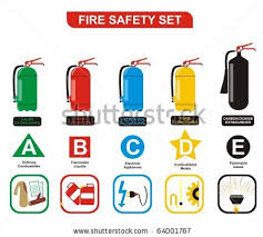
If there is a small electrical fire, be sure to use only a Class C or multipurpose (ABC) fire extinguisher, or you might make the problem worse. All fire extinguishers are marked with letter(s) that tell you the kinds of fires they can put out. Some extinguishers contain symbols, too.
The letters and symbols are explained below (including suggestions on how to remember them).
A(think: Ashes) = paper, wood, etc.
B(think: Barrel) = flammable liquids
C(think: Circuits) = electrical fires

All fire extinguishers are marked with a letter(s), which identifies the kinds of fires they put out. Sometimes the label is marked with both a letter and symbol. Be sure to read the label and use the appropriate extinguisher.
If there is a small electrical fire, be sure to use only a Class C or multipurpose (ABC) fire extinguisher, or you might make the problem worse. All fire extinguishers are marked with letter(s) that tell you the kinds of fires they can put out. Some extinguishers contain symbols, too.
The letters and symbols are explained below (including suggestions on how to remember them).
A(think: Ashes) = paper, wood, etc.
B(think: Barrel) = flammable liquids
C(think: Circuits) = electrical fires
All fire extinguishers are marked with a letter(s), which identifies the kinds of fires they put out. Sometimes the label is marked with both a letter and symbol. Be sure to read the label and use the appropriate extinguisher.
HOW ELECTRIC SHOCK IS RECEIVED?
Whenever you work with power tools or on electrical circuits, there is a risk of electrical hazards, especially electrical shock. Anyone can be exposed to these hazards at home or at work.
Workers are exposed to more hazards because job sites can be cluttered with tools and materials, fast-paced, and open to the weather. Risk is also higher at work because many jobs involve electric power tools.
Electrical trades workers must pay special attention to electrical hazards because they work on electrical circuits. Coming in contact with an electrical voltage can cause current to flow through the body, resulting in electrical shock and burns. Serious injury or even death may occur.
As a source of energy, electricity is used without much thought about the hazards it can cause. Because electricity is a familiar part of our lives, it often is not treated with enough caution. As a result, an average of one worker is electrocuted on the job every day of every year!
An electrical shock is received when electrical current passes through the body. Current will pass through the body in a variety of situations.
Whenever two wires are at different voltages, current will pass between them if they are connected. Your body can connect the wires if you touch both of them at the same time. Current will pass through your body.
In most household wiring, the black wires and the red wires are at 120 volts. The white wires are at 0 volts because they are connected to ground. The connection to ground is often through a conducting ground rod driven into the earth. The connection can also be made through a buried metal water pipe. If you come in contact with an energized black wire—and you are also in contact with the neutral white wire—current will pass through your body. You will receive an electrical shock.
If you are in contact with a live wire or any live component of an energized electrical device—and also in contact with any grounded object—you will receive a shock. Plumbing is often grounded. Metal electrical boxes and conduit are grounded.
Your risk of receiving a shock is greater if you stand in a puddle of water. But you don’t even have to be standing in water to be at risk. Wet clothing, high humidity, and perspiration also increase your chances of being electrocuted. Of course, there is always a chance of electrocution, even in dry conditions.
You can even receive a shock when you are not in contact with an electrical ground. Contact with both live wires of a 240-volt cable will deliver a shock. (This type of shock can occur because one live wire may be at +120 volts while the other is at -120 volts during an alternating current cycle—a difference of 240 volts.). You can also receive a shock from electrical components that are not grounded properly. Even contact with another person who is receiving an electrical shock may cause you to be shocked.
ELECTROCUTION AND ELECTRICAL FATALITIES BASIC INFORMATION
The term electrocution refers to an electrical event with electrical current exposure that results in death. The implication is that the current flow has caused an electrical shock with subsequent death.
“Electrical accident fatality” is a general use phrase seen in news reports meaning either electrocution, or death resulting at the time of the electrical accident. This phrase may include fatalities associated shock or other forms of energy released at the time of the electrical accident, in particular those causing physical changes including burns, blast effects, and radiation damage.
“Electrical injury mortality” is a medical statistics phrase which suggests that persons who were injured in an electrical accident lived long enough to receive medical care for their injuries, but the medical care was not followed by survival.
It’s important to appreciate that an electrical event can produce a fatality or injury even when there is no electrical current flow to the victim or electrical shock. This might be the situation, for example, when a victim is caught in an electrical ignition fire, explosion, or blast.
In this type of scenario, the “root cause” of the accident is electrical, but the mechanism of death or injury is from thermal, acoustic, radiation, or blast exposure related to electrothermal chemical (ETC) combustion.
Another way employees can be killed or injured after an electrical event is that they are surprised by an energized source, either through a spark, like a static “zap” to exposed skin, or through a noise, like a sharp “gunshot” type sound close to the head.
The surprise can lead to an unintended body movement which might be characterized as a “startle response.” If the startle occurs at the top of a ladder or scaffold, the direct mechanism of death or injury can be through a fall.
If the startle occurs in proximity to other energized equipment that is moving, the direct mechanism of death or injury can be with a body part being caught in or by the moving equipment.
Fatal and non-fatal electrical incidents share three characteristics:
1. The unintentional exposure of employees to electrical energy;
2. Compliance failure in at least one aspect of electrical design, installation, policies, procedures, practices, or personal protection; and
3. Energy transfer to exposed employees in some combination of electrical, thermal, radiation, acoustic (pressure), mechanical, light, kinetic, or potential energy.
What is the difference between fatal and non-fatal electrical incidents? The answer depends in part on whether the question is asked hypothetically, like in a “what if ” planning scenario; or whether the question is asked retrospectively after a traumatic accident has occurred.
Hypothetically, based on human physical and biological characteristics, we know that a fatal electrical event transfers a greater amount of energy to its victim than a non-fatal situation. This knowledge about the fatal risk of energy transfer underlies the use of equipment designs (for example, required doors, specified space clearances, venting systems on equipment to discharge combustion products, “umbilical corded” controls, infrared monitoring ports for doors closed heat monitoring) and barrier protection (such as PPE, including leather gloves, flash suits, safety glasses, face shields, long sticks, extended handles, and flame resistant clothing).
By reducing the amount of possible energy transfer during an unintentional electrical exposure, strategies including equipment design and barrier protection can increase the likelihood of survival after an electrical incident.
Retrospectively, if two people are present in an electrical incident when one dies and the other survives, the difference in survival may come down to nuances in the victims’ innate individual differences and their spatial and temporal relationship to the electrical hazard at the time of the energy release, transformation, and transfer. Medical and legal privacy protections tend to reduce accessibility to accident details, so systematic information is lacking about how various scenarios unfold.
Generally, there is a lethal exposure “dose” for different forms of energy that can result in death. When multiple forms of energy are involved in an electrical event, multiple lethal or sublethal doses of energy may flow from the event, transformed from the electrical hazard source, and transferred to nearby employees may result in highly variable damage to the body.
EFFECT OF CURRENT and ITS DURATION TO THE HUMAN BODY DURING ELECTRIC SHOCK
WHAT KILLS A PERSON? CURRENT OR VOLTAGE?
To answer the question, we need to put things in context. That means, there is no absolute. Current kills, but it needs to be present for a certain period of time.
The amount of energy delivered to the body is directly proportional to the length of time that the current flows; consequently, the degree of trauma is also directly proportional to the duration of the current. Three examples illustrate this concept:
1. Current flow through body tissues delivers energy in the form of heat. The magnitude of energy may be approximated by:
J = I2Rt
where J = energy, joules
I = current, amperes
R = resistance of the current path through the body, ohms
t = time of current flow, seconds
If sufficient heat is delivered, tissue burning and/or organ shutdown can occur. Note that the amount of heat that is delivered is directly proportional to the duration of the current (t).
2. Some portion of the externally caused current flow will tend to follow the current paths used by the body’s central nervous system. Since the external current is much larger than the normal current flow, damage can occur to the nervous system.
Note that nervous system damage can be fatal even with relatively short durations of current; however, increased duration heightens the chance that damage will occur.
3. Generally, a longer duration of current through the heart is more likely to cause ventricular fibrillation. Fibrillation seems to occur when the externally applied electric field overlaps with the body’s cardiac cycle. The likelihood of this event increases with time.
Also, we need to understand how much current is significant.
The magnitude of the current that flows through the body obeys Ohm’s law, that is,
I = E/R
where I = current magnitude, amperes (A)
E = applied voltage, volts (V)
R = resistance of path through which current flows, ohms (Ω)
Parts of the Body.
Current flow affects the various bodily organs in different manners. For example, the heart can be caused to fibrillate with as little as 75 mA.
The diaphragm and the breathing system can be paralyzed, which possibly may be fatal without outside intervention, with less than 30 mA of current flow. The specific responses of the various body parts to current flow are covered in later sections.
Nominal Human Response to Current Magnitudes
ELECTRIC SHOCK HAZARD ANALYSIS
WHAT HAPPENS WHEN WE GET ELECTRIC SHOCK?
Electric shock is the physical stimulation that occurs when electric current flows through the human body. The distribution of current flow through the body is a function of the resistance of the various paths through which the current flows. The final trauma associated with the electric shock is usually determined by the most critical path called the shock circuit. The symptoms may include a mild tingling sensation, violent muscle contractions, heart arrhythmia, or tissue damage.
Common effect are the following:
Burning.
Burns caused by electric current are almost always third-degree because the burning occurs from the inside of the body. This means that the growth centers are destroyed. Electric-current burns can be especially severe when they involve vital internal organs.
Cell Wall Damage.
Research funded by the Electric Power Research Institute (EPRI) has shown that cell death can result from the enlargement of cellular pores due to high-intensity electric fields. This research has been performed primarily by Dr. Raphael C. Lee and his colleagues at the University of Chicago. This trauma called electroporation allows ions to flow freely through the cell membranes, causing cell death.
HOW YOUR PHYSICAL CONDITION IS A FACTOR DURING ELECTRIC SHOCK
Physical Condition and Physical Response.
The physical condition of the individual greatly influences the effects of current flow. A given amount of current flow will usually cause less trauma to a person in good physical condition.
Moreover, if the victim of the shock has any specific medical problems such as heart or lung ailments, these parts of the body will be severely affected by relatively low currents. A diseased heart, for example, is more likely to suffer ventricular fibrillation than a healthy heart.
EMERGENCY LIGHTING SYSTEM DESIGN CONSIDERATIONS CODES AND STANDARDS
Emergency lighting is required when the normal lighting is extinguished, which can occur for any of three reasons:
1. General power failure
2. Failure of the building’s electrical system
3. Interruption of current flow to a lighting unit, even as a result of inadvertent or accidental operation of a switch or circuit disconnect.
As a result of the third reason, sensors must be installed at the most localized level—that is, at the lighting fixture (voltage sensor) or in the lighted space (photocell sensor).
Codes and Standards
Because emergency lighting is a safety-related item, it is covered by various codes, several of which may
have jurisdiction. In addition, there are widely accepted technical society and industry standards whose recommendations normally exceed the minimal required by codes.
1. Life Safety Code (NFPA 101, 2009). This code defines the locations within specific types of structures requiring emergency lighting and specifies the level and duration of the lighting.
2. National Electrical Code (NFPA 70, 2008). This code deals with system arrangements for emergency light (and power) circuits, including egress and exit lighting. It discusses power sources and system design.
3. Standard for Health Care Facilities (NFPA 99, 2005). This code deals with special emergency light and power arrangements for these facilities.
4. OSHA regulations. These are primarily safety oriented and, in the area of emergency lighting, discuss primarily exit and egress lighting requirements.
5. Industry standards. These include the publications of the IESNA and the IEEE, in particular Recommended Practice for Emergency and Standby Power Systems for Industrial and Commercial Applications (IEEE Standard 446-1995).
Because codes and standards are constantly being revised and updated, the designer for an actual project must determine which codes have jurisdiction, obtain current editions, and design to fulfill their requirements. The following material provides general information and focuses on good practice but is not intended to take the place of applicable construction and safety codes.
Subscribe to:
Posts (Atom)